


VFD and Servo Board Reverse Engineering: Gate Drive and Current Sensing
A variable-frequency drive is unusual hardware: two engineering worlds share the same copper. A high-voltage power stage switches at four to sixteen kilohertz while a low-voltage control section makes microsecond decisions a few millimetres away. When the manufacturer discontinues the board and the last spare is gone, PCB reverse engineering is the practical route back to a manufacturable design. Servo drives add a closed current loop to the same problem, so both families usually arrive together. It is a familiar corner of industrial PCB reverse engineering.
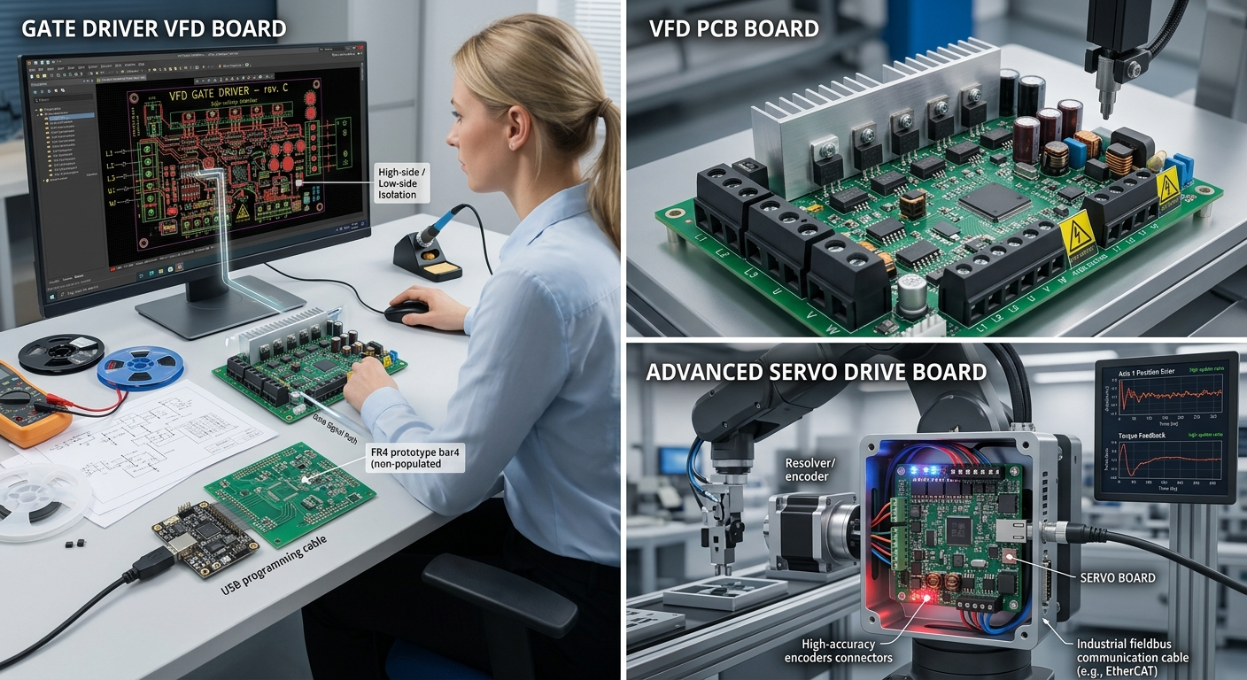
Why drive boards resist a part-by-part reading
Most industrial boards can be understood by reading their parts. A motor-drive board cannot, because much of its behaviour is set by timing rather than connectivity. Two assemblies with identical netlists can behave completely differently if the gate resistor, the dead-time or the sense filter differs.
Three elements dominate:
- Gate-drive topology — discrete totem-pole stage, dedicated gate-driver IC, or an isolated driver with its own floating supply.
- Current-sensing method — shunt with differential amplifier, Hall-effect sensor, or current transformer on the DC link.
- Protection logic — desaturation detection, overcurrent blanking, and fault latching that the controller must later clear.
None is visible in a netlist alone; all three must be measured on a live board.
Reading the gate-drive stage
The gate drive is the most frequently damaged and least frequently documented part of any VFD board reverse engineering investigation. Start with the supply, not the signal: a high-side driver needs a bootstrap capacitor or an isolated rail at the switching node’s potential. The bootstrap diode, the capacitor value and the refresh interval together set the minimum on-time — a parameter no netlist records.
Then measure the interface itself:
- Gate resistor value and its return path — this sets dv/dt, switching loss and radiated EMI in one number.
- Dead-time — either inside the driver IC or programmed by the controller; either way it must be recovered, because too little destroys the half-bridge.
- Desaturation blanking — the network that delays fault detection long enough to ignore switching noise.
- Star-point return — the Kelvin connection back to the emitter, which is what separates a clean edge from an oscillation.
Where a drive uses discrete gate circuitry, that information lives in a dozen passive values, each read rather than assumed. The auxiliary rails feeding those drivers deserve their own pass — the same discipline that applies to industrial power supply boards, where one feedback network controls everything downstream.
Current sensing defines torque, not voltage
The power stage decides how much voltage the motor sees. The current-sense chain decides what the controller believes about it. A drive with a sound power stage and a sloppy sense chain will run — and run badly.
Four parameters matter:
- Sensor position — a single DC-link shunt, phase-leg shunts, or isolated sensors on the motor leads.
- Gain and offset — including the divider that shifts a bipolar signal into the ADC’s unipolar range.
- Filter bandwidth — the RC ahead of the converter, which must pass the harmonics the control loop needs while rejecting the carrier.
- Isolation boundary — where the measurement crosses from the high-voltage domain into the control domain, and by what means.
Shunt-based sensing is harder: the amplifier’s common-mode range, the reference the converter compares against and the sample instant relative to the PWM carrier all interact. Measure the sampling instant with a scope at the ADC input while the drive runs, then confirm it against the controller’s timer configuration. Where the intent is a reusable, editable output rather than one replacement board, schematic recovery stops being a drawing exercise and becomes a measurement problem.
A recovery sequence for power boards
Order matters, because mistakes here are expensive:
- Photograph both sides and record every revision mark, date code and coating.
- Image or de-layer the copper, then extract the netlist layer by layer.
- Rebuild the schematic, resolving power-stage nodes by continuity measurement rather than inference.
- Measure the timing parameters — dead-time, blanking, sense filtering — on a powered board.
- Cross-check the result against nameplate ratings and, where a working drive exists, against its waveforms.
Steps three and four carry the accuracy: a single wrong inner-layer trace or mis-measured blanking network propagates silently into every board built from the data.
How this work is approached
Our team at Circuit Engineering Company Limited focuses on this class of hardware: industrial circuit boards, recovered from the physical board, delivered as editable data the client owns. The output is a netlist, a schematic, fabrication data and a bill of materials with substitutes for obsolete electronic components — so a plant can keep an old drive running without redesigning it.
Drive boards reward that discipline: an isolation problem, a timing problem and a measurement problem sharing one substrate. Read the power stage, the gate drive and the sense chain as three separate investigations and PCB reverse engineering becomes a sequence of measurements instead of a guess.