


SMPS Reverse Engineering: Feedback and Compensation
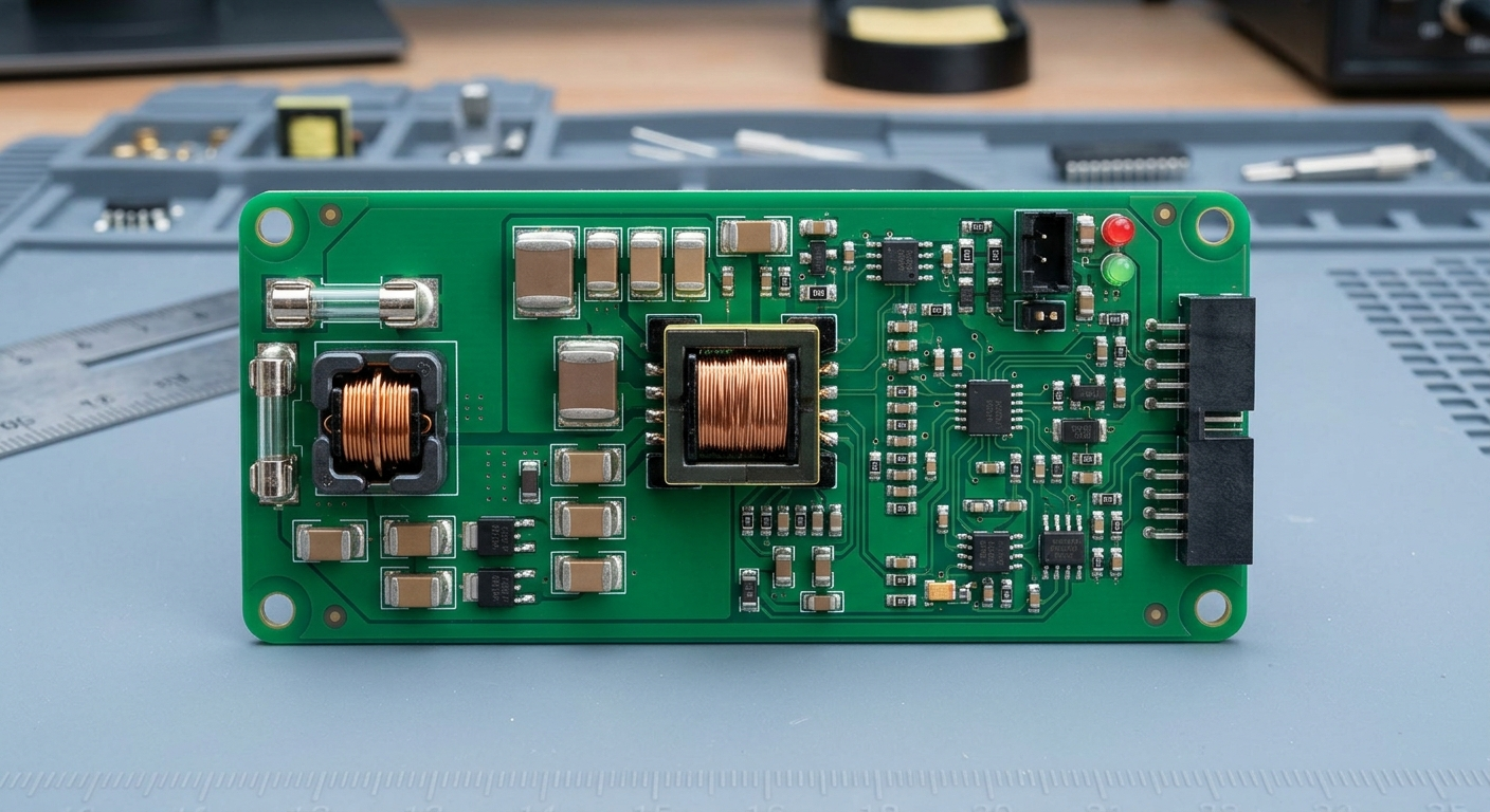
A switch-mode supply looks like the simplest board in an industrial cabinet: rectifier, bulk capacitor, controller, transformer, output capacitors. The parts list is short and mostly commodity; the design is not. What separates a supply that starts reliably on a cold morning from one that oscillates under load lives entirely in the loop — and the loop is the one thing copper does not record. That is why PCB reverse engineering of a power board is less about tracing tracks than recovering intent: which quantity the designer regulated, how the error crosses the isolation barrier, and how much phase margin was left deliberately. The same discipline runs through an established power-board workflow.
Why power boards hide their intent
A netlist from any SMPS reverse engineering pass lists every resistor and capacitor. It says nothing about what they do. Three classes of information stay invisible:
- The regulated quantity — output voltage, output current or a blend, and where the sense point sits.
- The compensation shape — the pole-zero pattern that sets crossover frequency and phase margin.
- The protection thresholds — undervoltage lockout, overvoltage, overcurrent, soft-start and slope compensation, each set by one passive value or transformer ratio.
A 10 kΩ resistor at a controller pin means nothing until you know whether the pin is a current-sense input or a feedback node. Identifying the silicon before reading values separates a trustworthy recovery from a plausible one.
Recovering the feedback path
The loop is reconstructed first: every other measurement is downstream of it.
Isolated designs: reference and optocoupler
In an isolated flyback or forward converter the error amplifier sits on the secondary. The classic arrangement is a shunt reference — a TL431 or equivalent — comparing a divider against its bandgap and driving an optocoupler LED. Two parameters must be measured, not read: the divider ratio that fixes the output voltage, and the optocoupler’s current-transfer ratio, which sets loop gain and drifts with temperature and age. A bias winding may also take over the controller’s supply after start-up, so both must be read as one mechanism.
Non-isolated DC-DC converters
Buck, boost and buck-boost stages are the common ground of DC-DC converter reverse engineering. The error amplifier sits inside the controller, and the divider from output to feedback pin is the whole user-facing design. What matters is whether the part runs in current or voltage mode, since that decides how compensation behaves and which node the designer could leave uncompensated.
Compensation and loop measurement
Networks on the COMP or FB pin are almost always Type II or Type III, and their values encode a crossover frequency and phase margin — neither of which appears in the copper. Where the board can be powered safely, measure directly: inject a small signal through an isolation transformer and sweep, or apply a step load and read the settling. Where it cannot, reconstruct the values from datasheet topology and confirm them on a rebuilt board.
The controller and its protection thresholds
Discontinued controllers are the usual reason a power board needs recovery; identification precedes analysis. Work through the pins methodically:
- Supply and enable — the start-up resistor, the auxiliary winding and the UVLO thresholds that gate operation.
- Current sense — the shunt or sense-FET tap, the RC filter ahead of it and any slope-compensation ramp.
- Feedback input — whether it accepts a divided voltage, an optocoupler current or a secondary-side amplifier.
- Protection and timing — overvoltage, over-temperature, soft-start and frequency pins, each worth measuring twice.
Where there is no drop-in replacement, the substitute must match start-up thresholds and drive strength, not just pinout — the problem that faces obsolete electronic components in legacy hardware, and why schematic recovery and sourcing go together.
A recovery sequence for switch-mode boards
Order matters — a wrong value here destroys silicon:
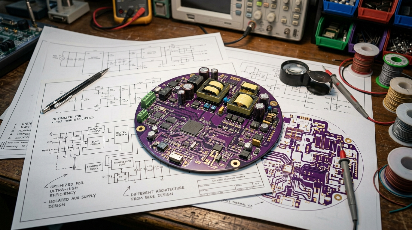
- Document the board: both sides photographed, revision marks, date codes and coating.
- Image or de-layer the copper; extract the netlist layer by layer.
- Identify every active device, beginning with the controller and gate drivers.
- Rebuild the schematic by continuity measurement, separating measured from inferred values.
- Power the board on an isolation transformer; record start-up, steady-state and fault waveforms.
- Verify the rebuilt design under load and at temperature extremes before releasing data.
Steps two and four carry the accuracy, and dominate the true cost of a PCB reverse engineering project — not the drawing, but the confidence behind each value.
Document the board: both sides photographed, revision marks, date codes and coating.
Image or de-layer the copper; extract the netlist layer by layer.
Identify every active device, beginning with the controller and gate drivers.
Rebuild the schematic by continuity measurement, separating measured from inferred values.
Power the board on an isolation transformer; record start-up, steady-state and fault waveforms.
Verify the rebuilt design under load and at temperature extremes before releasing data.
Steps two and four carry the accuracy, and dominate the true cost of a PCB reverse engineering project — not the drawing, but the confidence behind each value.
How this work is approached
Our team at Circuit Engineering Company Limited focuses on this class of hardware: industrial power supply boards, recovered from the physical board and delivered as editable data the client owns — netlist, schematic, fabrication data and a bill of materials.
Power boards reward patience: read the silicon first, treat the feedback path as a measurement problem rather than a drawing one, and PCB reverse engineering turns a black box into a schematic the plant can maintain for another decade.