

Reverse Engineering Printed Circuit Board Probing Technology
When Reverse Engineering Printed Circuit Board, the commonly used probing techniques are handheld, SMA, and microprobe. The choice of Reverse Engineering Printed Circuit Board Probing Technology depends on the accuracy needed and work involved to complete the measurements. These different methods will play a big role in correlation and repeatability.
The probe’s role is to provide a medium for transferring the pulse from the TDR’s reference 50Ω output to a particular load of interest. When the probe is not exactly 50Ω, an impedance discontinuity will occur between the TDR output and load of interest when Reverse Engineering Printed Circuit Board. This discontinuity will induce ringing and reflections on the pulse that results in larger inaccuracies. Ringing and reflections produce bumps and dips which ideally should be flat.
Reverse Engineering Printed Circuit Board Probing Technology
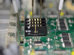
HANDHELD PROBE
The easiest, most commonly used probe in the process of Reverse Engineering Printed Circuit Board is the handheld probe with ground spanner. This is a good method for quick process variation checks but not good for determining real repeatable measurements.
SMA Connector
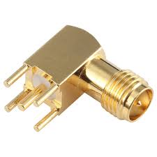
SMA connectors soldered to the board will provide good repeatability but require the cost of the SMA and soldering time. This is useful for correlation between vendors and customers.
The plots in figure 8 illustrate the repeatability differences between SMA connectors and handheld probe techniques . The SMA curves show good repeatability between instances of disconnecting and reconnecting the coax cable. The handheld probe curves exhibit variation due to different ground points.
Tags: reverse engineering circuit board,reverse engineering pcb,reverse engineering pcb assemble,reverse engineering pcb board,reverse engineering pcb card,reverse engineering pcb circuit board,reverse engineering pcba,reverse engineering printed circuit board,reverse engineering printed wiring board,reverse engineering pwb,reverse engineering pwba