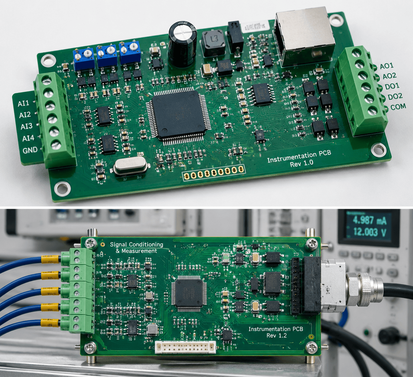
Instrumentation PCB Reverse Engineering: Isolated Front Ends and ADCs
Process instruments are analog boards with a serial port attached. A pressure transmitter, a load-cell indicator, a thermocouple module: each spends most of its circuitry turning microvolts into a number that survives a noisy cabinet. The hard part is not the microcontroller. It is the chain in front of it — protection, excitation, isolation, gain, conversion, reference — where one changed resistor or one downgraded amplifier moves the reading outside its certificate. Recovering such a board means measuring that chain rather than inferring it, and instrumentation PCB reverse engineering is largely the discipline of doing so in the right order.
The signal chain, in order
A front end is short and strictly ordered. Signal enters through protection and an RC filter, crosses an isolation barrier, is amplified and offset, then digitised against a reference. Four blocks decide whether a rebuild will match the original:
- Protection and filtering — TVS clamps, series resistors and a differential RC network that set both surge tolerance and noise bandwidth.
- Excitation — a constant current for RTDs, a stable bridge voltage for strain gauges; its tolerance becomes span error.
- Isolation — an isolated amplifier or modulator, plus a floating supply on the field side.
- Conversion — delta-sigma or SAR, and whether the reference is internal, external or ratiometric to excitation.
The last two are most often misread: both look ordinary until the markings are read closely.
Reading the isolation barrier
Amplifier or modulator
Two families dominate. An isolated amplifier of the HCPL-7840 or AMC1200 pattern outputs a differential analog signal that the host ADC samples; a delta-sigma modulator outputs a bitstream that the controller filters. The distinction sets everything downstream: an amplifier needs a differential input stage with adequate common-mode range, a modulator needs the correct clock and a matching decimation filter. Substituting one for the other will power up and read wrong.
Barrier power
Every barrier needs a floating rail, usually a small push-pull or flyback converter with a transformer, or a dedicated isolated DC-DC module. Record the switching frequency: it sits close to the signal bandwidth and appears as a periodic error when the post-filter is wrong.
What to measure
With the board powered from a known source, measure the field-side rail, the barrier input offset and the output common mode. Then inject a known millivolt signal at the terminals and record where it appears. Continuity proves nothing across an isolation barrier — the most common error in a first PCB reverse engineering pass on this class of board.
Gain, offset and reference
Where the scale lives
Gain is set by a resistor network around the amplifier or by the converter’s internal PGA. On 4–20 mA inputs a 100 Ω or 250 Ω sense resistor defines the conversion, and its tolerance and temperature coefficient are part of the specification rather than a detail. Offset may come from a trimmer, laser-trimmed resistors or firmware.
Calibration constants
Most instrument boards keep gain and offset coefficients in an EEPROM, with the analog hardware built to wide tolerances that those coefficients correct. If the memory is lost, the recovered schematic must ship with a calibration procedure; otherwise the design is complete on paper and out of tolerance on the bench. Knowing which coefficients are single-point and which two-point is documentation as much as electrical work.
The converter interface
Establish the bus first — SPI mode, word length, conversion rate — then the reference. A ratiometric design scales its result to the excitation supply, so dropping in a fixed reference breaks the temperature behaviour while leaving room-temperature readings plausible. Delta-sigma parts add a filter setting that changes noise and settling time together.
A recovery sequence for instrument boards
- Photograph both sides and every option link and trimmer position before cleaning.
- Trace input protection and filtering first; they define what the terminals can survive.
- Map the barrier and its floating supply, and confirm the device family.
- Rebuild the gain network and identify the sense or shunt element with its tolerance.
- Dump the calibration memory before touching the analog section.
- Verify against a known source at three points, then publish measured values apart from inferred ones.
How this work is approached
Our team at Circuit Engineering Company Limited works on industrial instrumentation of this kind, recovered from the physical board and delivered as editable data the client owns — netlist, schematic, fabrication data and a bill of materials. Netlist work benefits from a disciplined reverse engineering software flow, and the analog section is documented through schematic recovery so the next technician inherits reasoning rather than guesswork, alongside the wider industrial board family. Instrument front ends fail quietly: a drift of a few counts, a channel that reads low when the cabinet warms. Measure the barrier, the gain and the reference in that order, and PCB reverse engineering gives the instrument a documented analog path again — one that can be calibrated instead of merely replaced.