


Fieldbus Board Reverse Engineering: RS-485, CAN and Profibus
A CNC control built in the late 1990s is rarely one board. It is a rack: a motion card, a few I/O slaves, a handwheel pendant and a drive, all on one differential pair. When a card fails, the machine stays valuable — the mechanics, tooling and part programs are intact. What is missing is a schematic, because the OEM documented the machine and never the board. Recovery starts at the connector, and that is the order PCB reverse engineering has to follow.
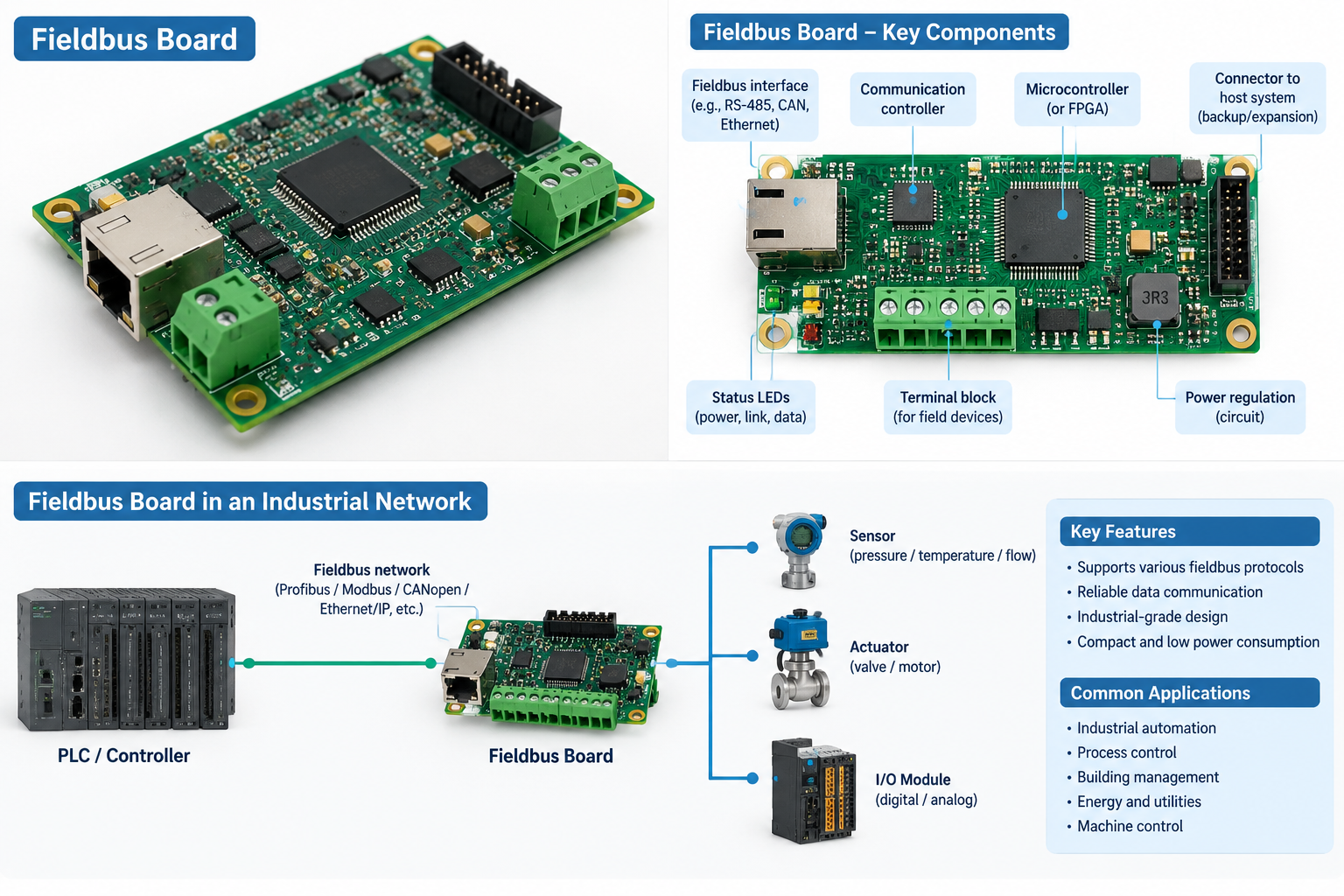
Where legacy control board reverse engineering begins
Almost every machine-tool network of that generation resolves to one of three standards, and each fails differently:
- RS-485 — a half-duplex multi-drop pair, terminated at both ends and biased to a defined idle state. Lose the bias and every frame becomes a framing error; double-terminate a short segment and it seems fine until the cable gets long.
- CAN — dominant and recessive levels on a terminated pair, usually split termination with a capacitor to ground. One transceiver stuck dominant takes the whole segment down, so a single dead node looks like a dead master.
- Profibus DP — RS-485 signalling with a three-resistor active termination inside the connector, from 9.6 kbit/s to 12 Mbit/s.
Reading the physical layer
Termination and bias
Termination parts identify the bus faster than markings. Two 120 Ω resistors with a split capacitor to ground say CAN; a T of 390/220/390 says Profibus; a single 120 Ω with pull-up and pull-down says RS-485. Unpowered, measure across the pair: two terminators read 60 Ω, one reads 120 Ω, three read 40 Ω.
Isolation and protection
Bus ports absorb the worst of plant wiring: TVS arrays, a common-mode choke usually in one four-line package, and PTC or fusible links ahead of the transceiver. Decide early whether the port is isolated — a DC-DC converter and digital isolator ahead of the transceiver mean the barrier is part of the design, and a substitute that drops it fails in the cabinet, not on the bench.
Connector conventions
Legacy pinouts disagree with themselves: Profibus on a DB9 puts B on pin 3 and A on pin 8, CAN puts CAN_L on 2 and CAN_H on 7, and terminal blocks label A and B however they like. Reversed A and B survives because a short, slow segment tolerates it — verify against copper, not silkscreen.
From transceiver to protocol engine
Behind the transceiver sits one of three arrangements. A UART in the microcontroller with a direction-control pin, where DE and RE are tied together and turnaround timing is firmware, not hardware. A CAN controller on a host interface, parallel-bus on older parts and inside the microcontroller on newer ones. Or a dedicated Profibus ASIC with its own eight-bit bus and shared-memory window, where configuration registers and the watchdog live.
The crystal is the most informative measurement on the board: CAN bit timing and Profibus baud are both divided down from it, so a drifted crystal produces errors that mimic protocol faults. Where markings are erased, package and pin count narrow the part.
What the copper cannot tell you, and the order to find it
Address, baud rate and drive parameters are set three ways, all three easy to destroy. DIP or rotary switches are the friendliest — photograph the positions first. Strap resistors read at boot come next. The third is a serial EEPROM read at start-up, and it is the most often missed: a rebuilt card with blank memory boots, reports healthy and refuses to move an axis. Any PCB reverse engineering pass that skips the memory hands back a board that works and a machine that does not.
Two items belong in the deliverable: the enable and interlock chain — relay contacts, opto inputs, a retriggered watchdog — and the handshake timing on any line the controller expects. A reasonable order:
- Photograph the card, switch positions and both connector faces.
- Power off. Measure across the pair against the expected termination.
- Power on, no traffic: check idle differential levels and bias.
- Scope the pair while the master polls, judging rise time before blaming the controller.
- Confirm clock, reset and watchdog — a board in reset looks protocol-dead and electrically fine.
- Read the configuration memory, then map transceiver, isolator and controller in that order.
How this work is approached
Circuit Engineering Company Limited works on industrial control boards of this age, recovered from the physical board and delivered as editable data the client owns — netlist, schematic, fabrication data and a bill of materials. Parts availability drives the schedule, so obsolete electronic components sourcing is planned early, and the netlist feeds schematic recovery under the same reverse engineering workflow.
A fieldbus card is a small computer in a hostile electrical environment, and most failures are in that part. Work outward from the pair, measure before replacing, and PCB reverse engineering turns an undocumented card into a node that can be diagnosed and rebuilt.