

Transmission Line Technique by PCB Reverse Engineering
Transmission Line Technique by PCB Reverse Engineering
The only way to preserve 1 ns or less rise/fall times over distances greater than about 2 inches without ringing is to use transmission line techniques by by PCB Reverse Engineering. below Figure shows two popular methods of termination: end termination and source termination.
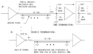
Termination Techniques for Controlled
The end termination method (above Figure part A) terminates the cable at its terminating point in the characteristic impedance of the microstrip transmission line. Although higher impedances can be used, 50 ohm is popular because it minimizes the effects of the termination impedance mismatch due to the input capacitance of the terminating gate (usually 5 pF to 10 pF).
Clock Distribution Using End-of-Line Termination
The source termination method, shown in above Figure, absorbs the reflected waveform with an impedance equal to that of the transmission line from PCB Reverse Engineering. This requires about 39 ohm in series with the internal output impedance of the driver, which is generally about 10ohm.This technique requires that the end of the transmission line be terminated in an open circuit, therefore no additional fanout is allowed. The source termination method adds no additional quiescent power dissipation to the circuit.
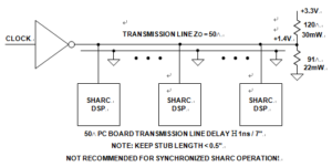
Below Figure shows a method for distributing a high speed clock to several devices. The problem with this approach is that there is a small amount of time skew between the clocks because of the propagation delay of the microstrip line (approximately 1 ns /7″). This time skew may be critical in some applications. It is important to keep the stub length to each device less than 0.5″ in order to prevent mismatches along the transmission line.
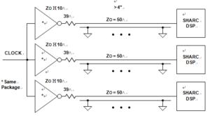
Preferred Method of Clock Distribution
The clock distribution method shown in below Figure minimizes the clock skew to the receiving devices by using source terminations and making certain the length of each microstrip line is equal. There is no extra quiescent power dissipation as would be the case using end termination resistors.