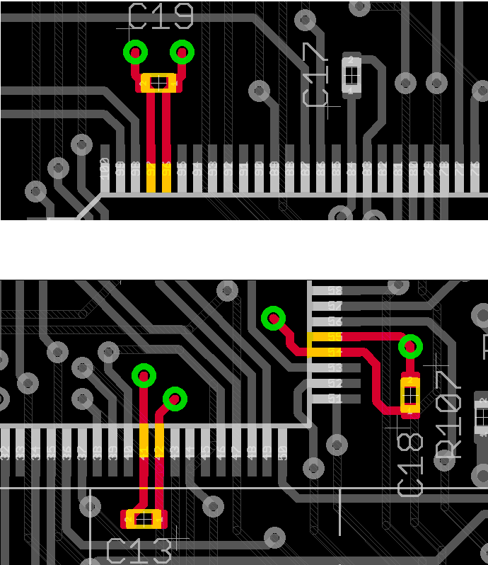
Printed Circuit Board Reverse Engineering Decoupling Capacitor
Why Printed Circuit Board Reverse Engineering Decoupling is important? Decoupling capacitors are an important part of any digital printed circuit board design. These capacitors are connected between power and power return conductors to help stabilize the voltage delivered to active digital devices.

Refers to Printed Circuit Board Reverse Engineering Decoupling, the Quantity of Distributed Decoupling Capacitors is very important (.01uf and 330pf)
The 22 pF capacitors were then replaced with 330 pF capacitors to determine the effect on the high frequency performance of S21 when Reverse Engineering PCB Board decoupling design.
For this set of experiments, the test PC board was completely populated with alternating .01 uf and 330 pF capacitors (all 99 locations had a .01 uF capacitor or a 330 pF capacitor, but not both values).
This set of experiments was again repeated for a number of different port-to-port combinations. Figure 26 shows the test result of various port-to-port configurations by cloning PCB card schematic.
The results show that at low frequencies, the S21 behavior is very similar to the case with only .01 uF capacitors. However, the improved low frequency performance is increased to a higher frequency with the addition of the second value of capacitor (330 pF) after PCB plate Reverse Engineering inspection.
Decoupling Around Board Edge Only
A set of experiments were conducted with the decoupling capacitors only around the outer edge of the test board. Figure 27 shows the various S21 port-to-port measurements for the case with only .01 uF capacitors, and Figure 28 shows the results when 10 pF capacitors are added.
Only the outer edge locations were populated with capacitors. There was no clear improvement with this configuration, and in fact, the fully populated board results were better, especially at low frequencies (below 400 MHz) before PCB Reverse Engineering.
Tags: pcb assemble reverse engineering,pcb board reverse engineering,pcb card reverse engineering,pcb reverse engineering,pcba reverse engineering,Printed Circuit Board Reverse Engineering,printed wiring board reverse engineering,pwb reverse engineering,pwba reverse engineering

