PWB Reverse Engineering Consider EMC’s Grounding Kill
PWB Reverse engineering Consider EMC’s Grounding Kill In the PWB reverse engineering, grounding is a very important measure to prevent the noise and prohibit the interference. The grounding method should be different due to the variation of circuit, the crosstalk among different circuit can be reduced or eliminated through correct grounding. There are two main grounding methods on PWB reverse engineering: single point grounding and multi-point grounding.
1 eliminate the grounding interference Under certain circumstance, it is not possible to avoid the interference bring by grounding impedancet, especially when view the grounding impedance as zero in terms of the electronic device is in ideal condition, it is not only the reference point in the signal electrical level, but no decreased pressure in the electronic device when current flow through it, it is a kind of ideal grounding line which never exist.
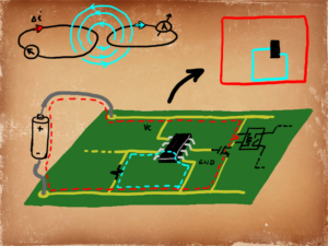
Grounding line has resistance and reactance simultaneously, when current flow will definitely has voltage drop down, on the other side, grounding line of PCB Board reverse engineering can make use of other lines to form the loop back, when the variable magnetic field cross loop back. 2 Principle of grounding line For the reverse engineering PWB with transmitting line length greater than 1/20 of max frequency, can be viewed as high frequency, on the contrary, should be viewed as low frequency. According to the principle, for the PWB circuit with lower than 1MHZ, it is better to apply single point grounding; as for frequency higher than 10MHZ, multi-point grounding of PCB Reverse Engineering is preferable. For the frequency among them, so long as the length of longest transmitting line is less than one twentieth of wavelength, single point should be applied to avoid the public resistance coupling.
Tags: pcb assemble clone,pcb board clone,pcb card clone,pcb clone,pcba clone,printed circuit board clone,printed wiring board clone,pwb clone,pwba clone


