

PCB Mounting Holes Design
PCB mounting holes help to fix the PCB to the housing. But this is its physical and mechanical purpose. In addition, in terms of electromagnetic functions, PCB mounting holes can also be used to reduce electromagnetic interference (EMI), as a result of that, PCB Mounting Holes Design will become much important for increasing electro-magnetic interference resistance capability;
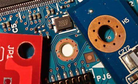
PCBs that are sensitive to EMI are usually placed in metal enclosures. In order to effectively reduce EMI, the plating PCB mounting holes need to be connected to the ground. After such grounding and shielding, any electromagnetic interference will be directed to the ground from the metal shell.
The common question that the average novice designer will ask is which ground do you connect it to? In common electronic equipment, there are signals, housing bases and grounding. According to the experience of an excellent electronic designer, the PCB mounting hole cannot be connected to the signal ground. The signal ground is the reference ground of the electronic components in your circuit design and it is not a good thing to introduce electromagnetic interference into it.
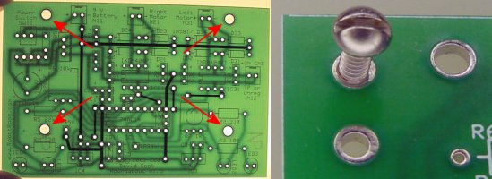
What is to be connected is the case ground. This is the confluence point of all the ground connections of the cabinet. The chassis ground should be connected at one point, which is a star connection. This can avoid causing ground loops and multiple ground connections. Multiple ground connections can cause a slight voltage difference and cause current to flow between the chassis grounds. Then connect the chassis ground to the ground to implement safety measures.