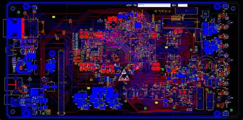
Printed Circuit Board Reverse Engineering Controlled Impedance Microprobes
Printed Circuit Board Reverse Engineering Controlled Impedance Microprobes operation can help to ensure the PCB board made through extracted layout drawing and gerber file which has impedance requirement whether they are differential ones or parallel ones can be met;

The most accurate probing technique of PCB Board Reverse Engineering layout rules uses controlled impedance microprobes shown in Figure 11for providing a full understanding of PCB characteristics. This technique requires specialized, costly, and setup-intensive equipment for obtaining measurements. It is the only method that can be used to extract small PCB variations, but is not well suited for high volume manufacturing after PCB Reverse Engineering.
Figure 12 and Figure 13 illustrate the TDR pulse response comparison between SMA and microprobes for the same test structure. The microprobe curve exhibits significantly less ringing of the pulse and much improved edge response at the open-circuited end of the test coupon.
It can be seen that measurement points along the SMA curve deviate from the microprobe curve of high speed Printed wiring Board Reverse Engineering. These are points at which one could take measurement data and attribute it to PCB process variation when, in reality, it is due to errors associated with the measurement technique.
The TDR provides a simple means for determining PCB impedance and propagation delay Characteristics. However, the actual data extraction from a test structure can be highly dependent on cursor positioning on the TDR pulse. This section outlines the general instrument setup necessary to obtain accurate, repeatable measurement results independent of probe type and test structure.
Tags: pcb assemble reverse engineering,pcb board reverse engineering,pcb card reverse engineering,pcb reverse engineering,pcba reverse engineering,Printed Circuit Board Reverse Engineering,printed wiring board reverse engineering,pwb reverse engineering,pwba reverse engineering

