

Route Layout Drawing from PCB Board Cloning
Route Layout Drawing from PCB Board Cloning
Before routing the layout of PCB drawing from PCB Board Cloning, there are numerous things that must be taken care of first. To start off, it may be useful to change the color of certain nets. For instance, your ground nets, power nets, and clock nets should each be changed to a distinct color to make them stand out and to ensure that they are not confused with other nets.
The reason for this is that these are very important nets that should be manually routed so that the traces are short and straight. This will help guarantee that your circuit is working at peak performance. We can start out by clicking on the “View Spreadsheet” icon and selecting nets when PCB Board Cloning.
A list of your nets will be given. You can begin by right clicking on your ground net and selecting change color. You can change this net to any color you want (avoid red since it will blend in with a copper pour). Do this for all of the important nets.
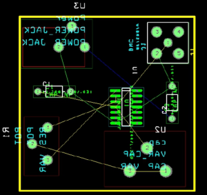
You can see that I have already done this in the image above (ground nets are green, power is blue). In the same spreadsheet, it is necessary to change the trace width. I recommend that you do not use a trace width any smaller then 15 mils, since there will be problems when etching after PCB Board Cloning.
To change the nets width, click on a net (or numerous nets by holding “CTRL”) and then right click and select “properties”. A box will appear as seen in below Figure.
place board layout