

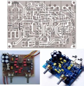
Reverse Engineering Printed Circuit Board Filter Option
The filtered TDR response Printed circuit board filter can be useful under conditions where excessive ringing occurs on the TDR pulse. The filtered response can be used for reverse engineering where the minimum edgerate is much larger than the TDR response. Enabling the filter function, filters unnecessary high frequency content on the TDR response.
This will provide a smoother curve increasing the ease to determine the impedance characteristics. The illustration below is an example of a filter response in comparison with normal unfiltered TDR response.
Reverse Engineering Printed Circuit Board Filter Option
As mentioned previously velocity measurements are more difficult and error – Prone by Reverse Engineering Printed Circuit Board. Accuracy will be very dependent on test structures, setup procedures and probe type.
Velocity measurements, extract the time it takes a pulse to propagate down a given test structure. Velocity is determined by measuring the pulse entering and exiting the test structure of a given length. The difficulty with these measurements to get accuracy within the picosecond domain is determining where to take the measurement on the curve of the pulse. The faster the rise-time of the pulse the less error.
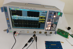
get accuracy within the picosecond domain is determining where to take the measurement
Note: It is recommended to use microprobes to complete any type of velocity measurement. Microprobes will provide the fastest rise-time launch into a coupon, therefore resulting in the best accuracy.
Tags: reverse engineering circuit board,reverse engineering circuit card,reverse engineering pcb,reverse engineering pcb assemble,reverse engineering pcb board,reverse engineering pcb card,reverse engineering pcba,reverse engineering printed circuit board,reverse engineering printed wiring board,reverse engineering pwb,reverse engineering pwba