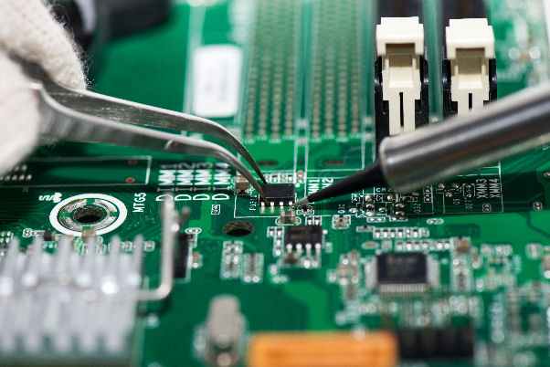
Reverse Engineering PCB Board for Velocity Measurement
Reverse Engineering PCB Board especially the high speed multilayer one needs to take the velocity measurement into account since it will greatly affect the performance of PCB board and accuracy of PCB board copying;

When Reverse Engineering PCB Board, velocity measurements are more difficult and susceptible to measurement errors. Accuracy is very dependent on test structures, setup procedures and probe types.
Velocity measurements upon PCB Board circuit diagram restoration will decide the time it takes a pulse to propagate down a given test structure. The difficulty to get accuracy within the picosecond domain with these measurements is determining exactly where to take the measurement on the curve (rise-time) of the pulse. The faster the rise-time of the pulse the less error when extract wiring diagram from PCB Board.
The easiest, most commonly used method to extract velocity after reverse engineering pcb board is to TDR two different open-ended coupons that differ only in length. Velocity is determined by subtracting the reflected delay differences between the two structures. The purpose of two test structures from reverse engineering pcb board is to null out determining the point where the pulse enters the test structure.
The easiest, most commonly used method to extract velocity after reverse engineering pcb board is to TDR two different open-ended coupons that differ only in length. Velocity is determined by subtracting the reflected delay differences between the two structures. The purpose of two test structures from reverse engineering pcb board is to null out determining the point where the pulse enters the test structure.
To make this measurement, maximize the TDR time base and position the cursors at the point where the reflected pulse begins to rise as illustrated in Figure 19. The ∆T value as shown will be twice the actual delay difference due to reflection, delay down and back from reverse engineering pcb. The delay per unit length is calculated by:
Delay/unit length = (∆T/2)/ (length difference)
Tags: reverse engineering circuit board,reverse engineering circuit card,reverse engineering pcb,reverse engineering pcb assemble,reverse engineering pcb board,reverse engineering pcb card,reverse engineering pcba,reverse engineering printed circuit board,reverse engineering printed wiring board,reverse engineering pwb,reverse engineering pwba

