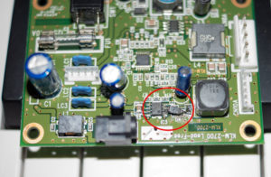
Reverse Engineering PCB Board Sideroad Capacitor Installation
Sideroad capacitor usually play the role of decrease the transient power supply requirement on the power module beside the high frequency component. Normally aluminum capacitor and tantunm capacitor is more suitable for sideroad when reverse engineering PCB board. And its value depends on the on transient current requirement on the PCB board, normally 10-470LF, if there are lots of integrated circuit , high speed switch on/off and power supply with long lead, then great capacitance capacitor should be chosen.

Reverse Engineering PCB Board Sideroad Capacitor Installation
3.3 Decoupling Capacitor installation
1> connect 10-100LF electro on the power supply output terminal, use 100LF is better if possible;
2> fundamentally all the integrated circuit chip should be placed a 0.01pf ceramic capacitor on the PCB board, if there is not sufficient space on the PCB board, can spare one piece of 1-10PF tantalum capacitor on every 4-8 piece of chips;
3> as for the component with great change when power off the supply or with weak capability to resist noise, such as RAM, ROM memorizer, decoupling capacitor should be reverse engineering PCB board directly among the power track and grounding track;
4> the capacitor lead shouldn’t be too long especially there shouldn’t be any lead on the side of high frequency capacitor;
5> since there is contact, relay and press button in the PCB board which will cause great discharge current must apply RC circuit to absorb the discharge current, and R is 1-2K, C is 2.2-47LF;
6> CMOS has high input impedance and quite sensible, so it is unused terminal should be connected to grounding or anode side.
Tags: reverse engineering circuit board,reverse engineering circuit card,reverse engineering pcb,reverse engineering pcb assemble,reverse engineering pcb board,reverse engineering pcb card,reverse engineering pcba,reverse engineering printed circuit board,reverse engineering printed wiring board,reverse engineering pwb,reverse engineering pwba

