"Everything we build starts with design engineering. CECL manufactured boards for one of our products. It went perfectly – a real success.It is really an high quality service they have provided to us!"
By Nile Smith from Sinotech Inc.
“We had several very old device with obsolete boards need to be replaced –through CECL professional service.We got what we needed, and we’ve been using the results of the work without any problem till now.”
By Richard Anderson from TWP system Inc.
"Guys from CECL manufacture PCBs we use in one of our products, a clinometer and we’ve never had a problem with anything. The boards come in, they work. And, their team is very responsive."
Bei der Anordnung elektronischer Bauteile auf der replizierten ECU-Leiterplatte beeinflusst die Platzierungsstrategie direkt die Signalintegrität, die elektromagnetische Verträglichkeit und die thermische Stabilität. Hochgeschwindigkeits-Mikrocontroller-Sektionen müssen nahe an ihren Entkopplungskondensatoren positioniert werden, um die Schleifeninduktivität zu minimieren. Einspritztreiberschaltungen, die höhere Ströme verarbeiten, sollten von empfindlichen analogen Eingängen zur Drehzahl- und Drehmomentmessung des Motors isoliert werden. Während der Reverse-Engineering- und Redesign-Phasen optimieren Ingenieure häufig das Layout, um die Erdungstrennung zwischen digitalen, analogen und Leistungsdomänen zu verbessern. Beim Nachbilden des ursprünglichen Routings kann die Masseflächenstrategie repliziert und die Rückleitungsdurchgängigkeit wiederhergestellt werden, um Störungen zu vermeiden. Die Bauteilgruppierung sollte den in dem rekonstruierten Schaltplan und der validierten Netzliste identifizierten Funktionsblöcken folgen. Darüber hinaus müssen Spannungsregler und wärmeerzeugende Bauteile so angeordnet werden, dass die Luftzirkulation und die Wärmeableitung durch Kupfer optimiert werden, um einen stabilen Betrieb unter Dauerlast zu gewährleisten. Jede Platzierungsentscheidung muss mit der verifizierten Stückliste übereinstimmen, um die Konsistenz von Grundfläche und elektrischer Nennleistung bei der Reproduktion und Duplizierung sicherzustellen.
Kopyalanan ECU baskılı devre kartı üzerindeki elektronik bileşenleri yerleştirirken, yerleştirme stratejisi sinyal bütünlüğünü, elektromanyetik uyumluluğu ve termal kararlılığı doğrudan etkiler. Yüksek hızlı mikrodenetleyici bölümleri, döngü endüktansını en aza indirmek için ayırma kapasitörlerine yakın konumlandırılmalıdır. Daha yüksek akım taşıyan enjektör sürücü devreleri, motor hızı ve tork algılama için kullanılan hassas analog girişlerden izole edilmelidir. Tersine mühendislik ve yeniden tasarım aşamalarında, mühendisler genellikle dijital, analog ve güç alanları arasındaki topraklama bölümlendirmesini iyileştirmek için yerleşim çizimini iyileştirirler. Orijinal yönlendirmeyi yeniden oluştururken, ekipler gürültü enjeksiyonunu önlemek için topraklama düzlemi stratejisini kopyalayabilir ve dönüş yolu sürekliliğini geri yükleyebilir. Bileşen gruplaması, kurtarılan şematik diyagramda ve doğrulanmış netlistte tanımlanan fonksiyonel blokları takip etmelidir. Ek olarak, güç regülatörleri ve ısı üreten bileşenler, sürekli yük altında kararlı çalışma sağlamak için hava akışını ve bakır ısı yayılımını optimize edecek şekilde düzenlenmelidir. Her yerleştirme kararı, yeniden üretim ve kopyalama sırasında ayak izi ve elektriksel değerde tutarlılığı korumak için doğrulanmış malzeme listesiyle uyumlu olmalıdır.
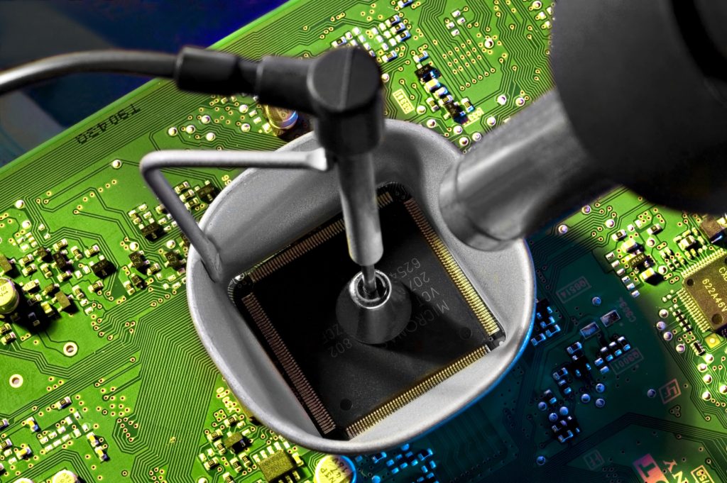
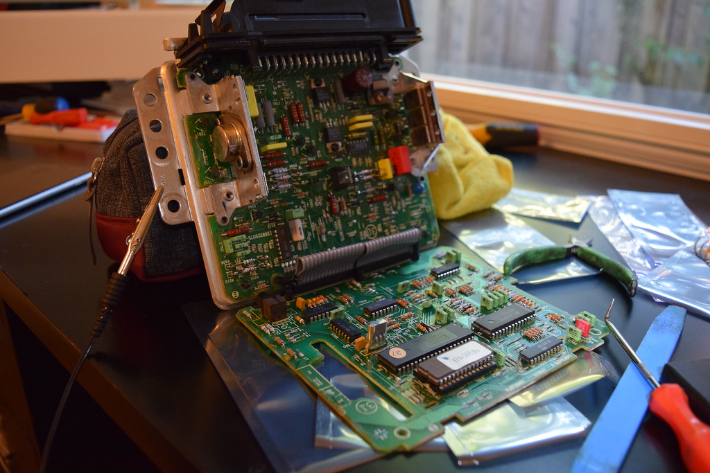
Replicate Printed Wiring Board for Component Arrangement which has been viewed as Bill of material, this documents can be obtained by reverse engineering pc board;
Replicate Printed Wiring Board for Component Arrangement which has been viewed as Bill of material, this documents can be obtained by reverse engineering pc board
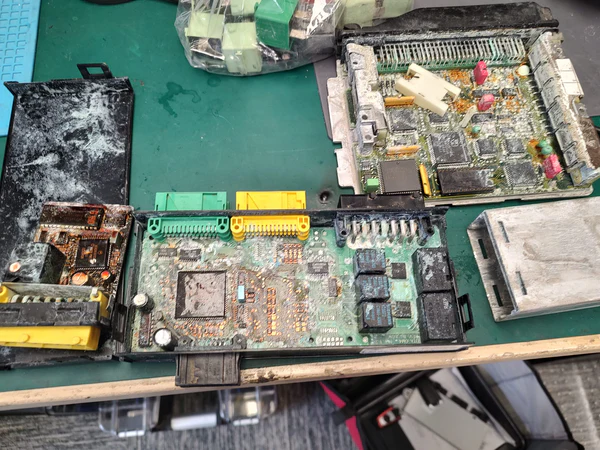
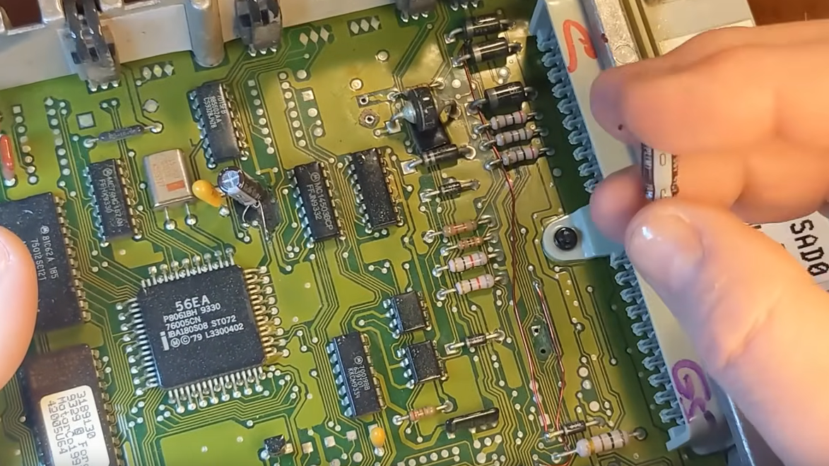
Clone PCB Card technology also include the component arrangement on it, in the process of determine Printed Wiring Board material, it is lay-up structure, dimension and functionality block system, component arrangement should be the next step to be taken into consideration, and it include place all of the electronic components onto the proper places of Printed Wiring Board. Appropriate electronic components arrangement on the Printed Wiring Board can strength its electronic magnetic compatibility which is also a necessary premise.
1, shorten the distance of electrical wire which connect the high frequency component, and decrease their distribution parameters and mutual electro-magnetic interference. And those components which is more tend to be interfered by electro-magnetic shouldn’t be layout too close, and output and input components shouldn’t be placed too close;
2, and some components could probably have high electrical level difference between other circuits, and their distance should be widen to avoid the short circuit accidently by static discharge or something when PCB reverse engineering software, and those components with high voltage should be placed on the area where the bare hand won’t be reachable in the process of Printed Wiring Board debugging and adjustment;
Quando si dispongono i componenti elettronici sulla scheda di cablaggio stampata della centralina replicata, la strategia di posizionamento influisce direttamente sull’integrità del segnale, sulla compatibilità elettromagnetica e sulla stabilità termica. Le sezioni del microcontrollore ad alta velocità devono essere posizionate vicino ai rispettivi condensatori di disaccoppiamento per ridurre al minimo l’induttanza di loop. I circuiti di pilotaggio degli iniettori, che gestiscono correnti più elevate, devono essere isolati dagli ingressi analogici sensibili utilizzati per il rilevamento della velocità e della coppia del motore. Durante le fasi di reverse engineering e riprogettazione, gli ingegneri spesso perfezionano il disegno del layout per migliorare la segmentazione della messa a terra tra i domini digitale, analogico e di potenza. Durante la ricostruzione del percorso originale, i team possono replicare la strategia del piano di massa e ripristinare la continuità del percorso di ritorno per prevenire l’iniezione di rumore. Il raggruppamento dei componenti deve seguire i blocchi funzionali identificati nello schema elettrico recuperato e nella netlist convalidata. Inoltre, i regolatori di potenza e i componenti che generano calore devono essere disposti in modo da ottimizzare il flusso d’aria e la diffusione del calore in rame, garantendo un funzionamento stabile durante il carico continuo. Ogni decisione di posizionamento deve essere allineata alla distinta base verificata per mantenere la coerenza di ingombro e potenza elettrica durante la produzione di riproduzione e duplicazione.
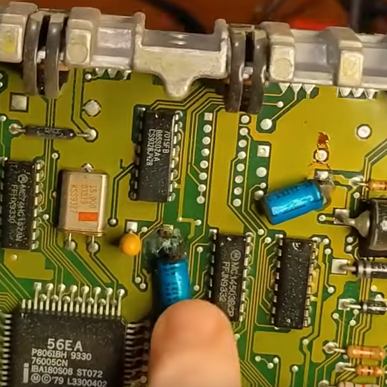
3, those components with weight over than 15kilograms should be supported by fixed bracket and then soldering it. As for those parts with heavy weight and great thermal dissipation, they are not suitable for assemble on the it, they should be installed on the enclosure plate for the sake of heat sink issue;
4, as for these potentiometer, adjustable conductance coil and adjustable switch should consider the structure requirement of whole Printed Wiring Board. If the adjustment is made inside the enclosure, then these parts should be layout on the reachable places, even outside the Printed Wiring Board, then it should have a direct connection with the adjustable button on the enclosure.
Lors de l’agencement des composants électroniques sur le circuit imprimé du calculateur (ECU) répliqué, la stratégie de placement influe directement sur l’intégrité du signal, la compatibilité électromagnétique et la stabilité thermique. Les sections de microcontrôleur haute vitesse doivent être positionnées au plus près de leurs condensateurs de découplage afin de minimiser l’inductance de boucle. Les circuits de commande d’injecteurs, qui supportent des courants plus élevés, doivent être isolés des entrées analogiques sensibles utilisées pour la détection du régime moteur et du couple. Lors des phases de rétro-ingénierie et de reconception, les ingénieurs affinent souvent le schéma d’implantation pour optimiser la segmentation de la masse entre les domaines numériques, analogiques et d’alimentation. Lors de la reconstitution du routage d’origine, les équipes peuvent reproduire la stratégie du plan de masse et rétablir la continuité du chemin de retour afin d’éviter l’injection de bruit. Le regroupement des composants doit suivre les blocs fonctionnels identifiés dans le schéma récupéré et la netlist validée. De plus, les régulateurs de puissance et les composants générant de la chaleur doivent être agencés de manière à optimiser la circulation de l’air et la dissipation thermique du cuivre, garantissant ainsi un fonctionnement stable sous charge continue. Chaque décision de placement doit être conforme à la nomenclature validée afin de maintenir la cohérence de l’encombrement et des caractéristiques électriques lors de la reproduction et de la duplication.
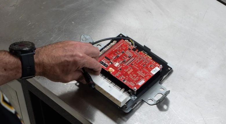
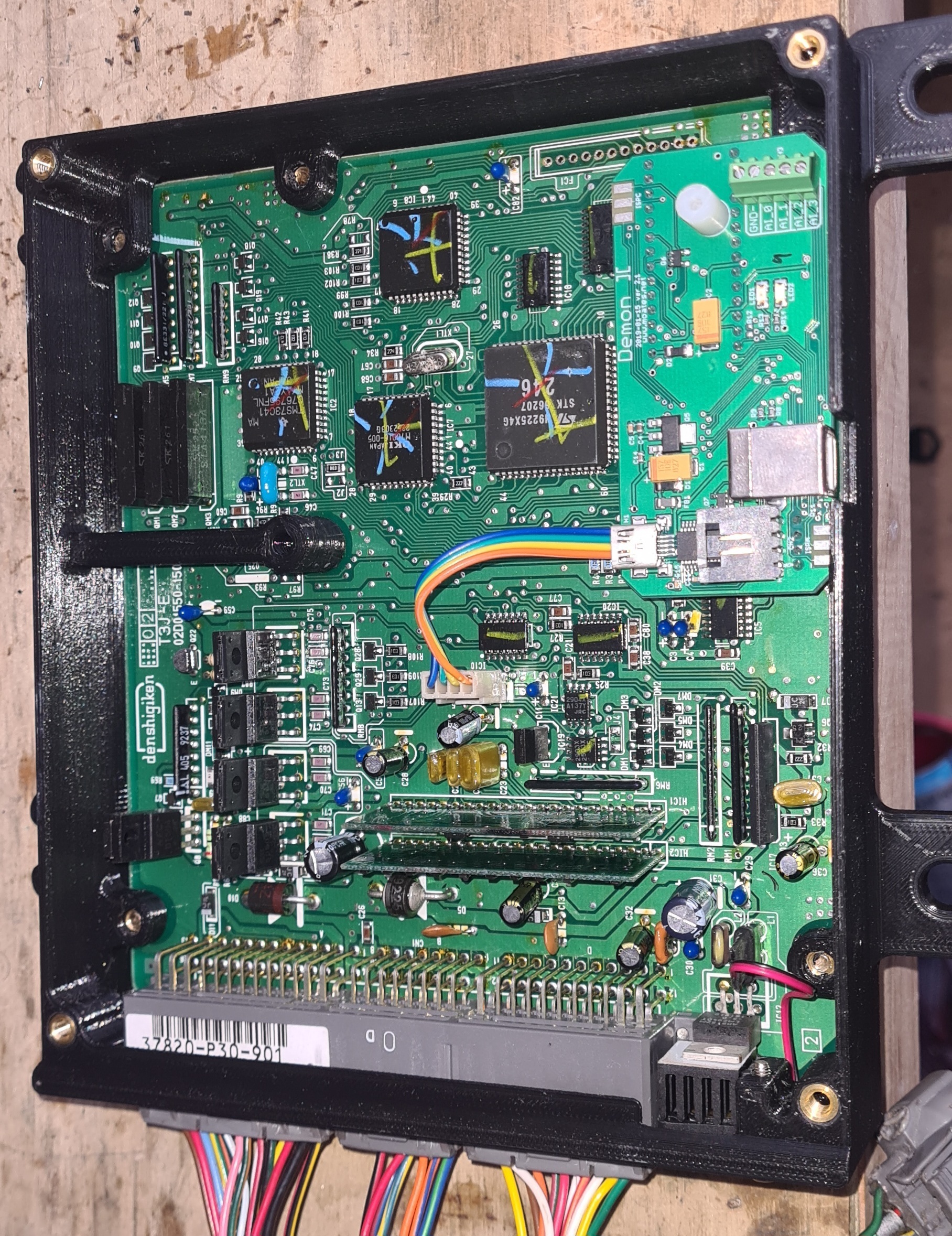
When arranging electronic components on the replicated ECU printed wiring board, placement strategy directly affects signal integrity, electromagnetic compatibility, and thermal stability. High-speed microcontroller sections must be positioned close to their decoupling capacitors to minimize loop inductance. Injector driver circuits, which handle higher current, should be isolated from sensitive analog inputs used for engine speed and torque sensing. During reverse engineering and redesign stages, engineers often refine the layout drawing to improve grounding segmentation between digital, analog, and power domains. While recreating the original routing, teams may replicate the ground plane strategy and restore return path continuity to prevent noise injection. Component grouping should follow functional blocks identified in the recovered schematic diagram and validated netlist. Additionally, power regulators and heat-generating components must be arranged to optimize airflow and copper heat spreading, ensuring stable operation during continuous load. Every placement decision must align with the verified bom list to maintain consistency in footprint and electrical rating during reproduce and duplicate production.
The final stage involves prototype validation and production preparation. After restoring documentation and arranging components according to optimized layout principles, engineers fabricate sample boards using the finalized Gerber file. Electrical testing verifies that engine speed monitoring, torque calculation, and fuel injection timing operate identically to the original ECU. If deviations appear, controlled redesign or redevelopment may be applied without altering fundamental control algorithms. Environmental stress testing—including vibration, thermal cycling, and load simulation—confirms that the remanufactured board meets operational durability standards. Once validated, the complete documentation package, including schematic diagram, netlist, layout drawing, bom list, and Gerber file, supports scalable clone and replicate production. Through disciplined reverse engineering, precise component arrangement, and systematic verification, organizations can confidently reproduce and refurbish wheel loader ECU printed wiring boards while maintaining high-performance engine control and long-term reliability.
रेप्लिकेटेड ECU प्रिंटेड वायरिंग बोर्ड पर इलेक्ट्रॉनिक कंपोनेंट्स को अरेंज करते समय, प्लेसमेंट स्ट्रेटेजी सीधे सिग्नल इंटीग्रिटी, इलेक्ट्रोमैग्नेटिक कम्पैटिबिलिटी और थर्मल स्टेबिलिटी पर असर डालती है। लूप इंडक्टेंस को कम करने के लिए हाई-स्पीड माइक्रोकंट्रोलर सेक्शन को उनके डीकपलिंग कैपेसिटर के पास रखना चाहिए। इंजेक्टर ड्राइवर सर्किट, जो ज़्यादा करंट हैंडल करते हैं, उन्हें इंजन स्पीड और टॉर्क सेंसिंग के लिए इस्तेमाल होने वाले सेंसिटिव एनालॉग इनपुट से अलग रखना चाहिए। रिवर्स इंजीनियरिंग और रीडिज़ाइन स्टेज के दौरान, इंजीनियर अक्सर डिजिटल, एनालॉग और पावर डोमेन के बीच ग्राउंडिंग सेगमेंटेशन को बेहतर बनाने के लिए लेआउट ड्राइंग को बेहतर बनाते हैं। ओरिजिनल रूटिंग को फिर से बनाते समय, टीमें ग्राउंड प्लेन स्ट्रेटेजी को रेप्लिकेट कर सकती हैं और नॉइज़ इंजेक्शन को रोकने के लिए रिटर्न पाथ कंटिन्यूटी को रिस्टोर कर सकती हैं। कंपोनेंट ग्रुपिंग को रिकवर किए गए स्कीमैटिक डायग्राम और वैलिडेट नेटलिस्ट में पहचाने गए फंक्शनल ब्लॉक्स को फॉलो करना चाहिए। इसके अलावा, पावर रेगुलेटर और हीट-जेनरेटिंग कंपोनेंट्स को एयरफ्लो और कॉपर हीट स्प्रेडिंग को ऑप्टिमाइज़ करने के लिए अरेंज किया जाना चाहिए, ताकि लगातार लोड के दौरान स्टेबल ऑपरेशन पक्का हो सके। हर प्लेसमेंट डिसीजन को वेरिफाइड बॉम लिस्ट के साथ अलाइन होना चाहिए ताकि रिप्रोड्यूस और डुप्लिकेट प्रोडक्शन के दौरान फुटप्रिंट और इलेक्ट्रिकल रेटिंग में कंसिस्टेंसी बनी रहे।