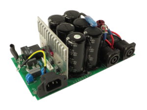
Power Supply PWB Reverse Engineering
Power Supply PWB Reverse Engineering has widely connection with other functional units, from one side the useless signal generated from power supply PWB can easily coupling into other functional units, from another side, the useless signals in a unit can probably coupling into other units through the common impedance of power supply. As a result of that, there are below measures must be taken:
1> Increase the power supply line width as much as possible according to the current on the PWB, reduce the loop back resistor, and serve to same orientation for both power supply line and grounding line as well as the transmitting orientation. At the same time, apply power supply layer and grounding layer in the multilayer PWB reverse engineering, reduce the line length from power supply layer or grounding layer which can improve the ability of noise interference resistance;
2> Power supply provide the power to each unit individually in the possible situation, all the tracks who use common power supply should be reverse engineeringed as close as possible and incompatible.
3> Reverse engineering the power supply wave filter on the AC/DC main line to prevent the external interference enter into PWB through power supply, prevent the switch transition and other signal generated from internal device enter into the preliminary power supply by reverse engineering PCB Board, isolate the input and output tracks on the power supply as well as the wave filter.
4> Effective electro-magnetic shielding on power supply when reverse engineering PWB, isolate high voltage power supply with sensitive circuit especially for switch power supply, which can cause high frequency radiation and transmission interference. Use power supply transformer with ESD shielding to suppress the common code interference on the power supply line. Multiple shielding isolated transformer can have better functions.
5> For all the circuit functional state, power supply should keep low output impedance, the output capacitor should express low impedance even within the frequency scope, at the same time, manostat should be given fast enough responding speed to bate the high frequency ripple wave and transition load.
6> when reverse engineering printed circuit board commutation diode, it should work in the lowest density current, provide sufficient radio frequency side road for zener diode;
7> Power supply transformer should be balanced and sync, not suppose to power balance. The metal core material should choose the lower limit value of saturation induction density. No matter how, the iron core should not in the state of saturation when reverse engineering PCB, the iron core of transformer should choose D type, C type, the E type is worst.
Tags: pcb assemble reverse engineering,pcb board reverse engineering,pcb card reverse engineering,pcb reverse engineering,pcba reverse engineering,Printed Circuit Board Reverse Engineering,printed wiring board reverse engineering,pwb reverse engineering,pwba reverse engineering


