

PCB Reverse Engineering General Setup
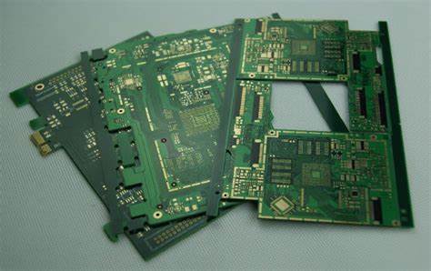
PCB Reverse Engineering General Setup include electronic components disasembly over the PCB board, scrub the solder resist layer off the origina Printed circuit board by physical method or chemical method;
Prior to initialization of PCB Reverse Engineering, put on the grounding strap and connect the cable and probe to the TDR channel that will be used for measurements using the torque wrench.
Measurements need to be completed with the board laying on nonconductive surface with microstrip traces faced up (air). While probing, the user must not touch the probe or trace that is being measured.
The test environmental conditions of PCB copying service must follow the Tektronix equipment specified environmental operating conditions.
Procedure
- · Connect cable and probe to Sampling head
- · Push Utility Button
Select initialize(touch Screen)
Select initialize under Verify(touch screen)
- · Push Trigger Button
Select Source(touch screen)
Select Internal Clock(touch screen)
- · Push Select Channel button on TDR Head
(Yellow light should begin flashing to indicate head is on and flat line should appear on the screen)
- · Push Waveform Button
Select Head Fcn’s(touch screen)
– Select channel(touch screen)
– Select TDR/TDR to ON(touch screen)
– Select Smoothing to ON(touch screen)
- · Select Graticules(touch screen)
Select rho(touch screen)
Select Acquire Desc(touch screen)
– Select Avg to ON(touch screen)
– Select Set AVGN(touch screen). Use upper Knob to set avgn=8
Push Auto Set Button. Screen should look similar to Figure 24.
For high volume manufacturing certification and testing, the instrument must follow the long-term stability procedures. This is necessary to determine instrument control charts after Regenerate PCB board documents.
The TDR sampling head must be on for a minimum of 30 minutes prior to any calibration and measurements.
Procedure
- · Calibration should be completed only after a control chart violation.
- · Disconnect cable and probe from instrument
- · Push Utility button
Select Page to Enhance Accuracy(touch screen)
Select Offset(touch screen)
– Select Auto Cal(touch screen)
– Terminate TDR head with 50 Ohm load
– Select Proceed(touch screen)
– Select Store Const(touch screen)
- · Select TDR Amplitude(touch screen)
Select Auto Cal(touch screen)
Terminate TDR head 50 Ohm load
Select Proceed(touch screen)
Select Store Const(touch screen)
Tags: pcb assemble reverse engineering,pcb board reverse engineering,pcb card reverse engineering,pcb reverse engineering,pcba reverse engineering,Printed Circuit Board Reverse Engineering,printed wiring board reverse engineering,pwb reverse engineering,pwba reverse engineering