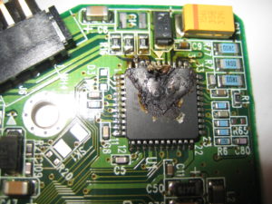
PCB Circuit Reverse Engineering Process
PCB Circuit Reverse Engineering need to understand the details of electronic circuit connection, which include below aspects:
1: Schematic diagram, include the electronic components detail information, connection and side connector parameters;
2: Component list, include the component name, size, part number and manufacturer;
3: mechanic specification, include the pcb circuit size and shape, fixed hole, marks of component height limitation, location of side part connector,etc;
4: PCB circuit specification, single side, double side or multilayer PCB circuit, has or hasn’t through hole;
5: PCB circuit drawing specification: include soldering pad type and size, track width and space;
6: Electrical specification, such as component placement should be limited by the heat when operation, capacitor and inductor coupling, critical length of grounding;
First of all, prepare the component list and library, it will describe all the necessary components footprint, include the exterior, pad type, size and pad location. In the complete component list, should indicate each one of component’s footprint, component’s name and location. The list should give the clear description of each component.
PCB Reverse Engineering final detail information should include pcb circuit specification and the X/Y coordinate on the corner. The correctiveness of These datas, especially the electrical connection are all critical importance. In many CAD system, has been regulated to have isolated operators to reverse engineering PCB circuit separately for the same circuit connection. Only the exclusion of the difference between these connected list, the next step can be proceeded.
Tags: pcb assemble reverse engineering,pcb board reverse engineering,pcb card reverse engineering,pcb reverse engineering,pcba reverse engineering,Printed Circuit Board Reverse Engineering,printed wiring board reverse engineering,pwb reverse engineering,pwba reverse engineering


