

PCB Card Inductors’ Quality Factor
An important characteristic is PCB Card Inductors’ Quality Factor, which is the ratio of the reactive impedance to the resistance, as indicated in below Figure:
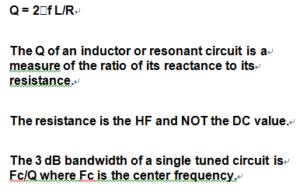
Inductor Q or Quality Factor
It is rarely possible to calculate the Q of an inductor from its dc resistance, since skin effect (and core losses if the inductor has a magnetic core) ensure that the Q of an inductor at high frequencies is always lower than that predicted from dc values.
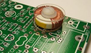
PCB Card Inductors’ Quality Factor
Q is also a characteristic of tuned circuits (and of capacitors—but capacitors generally have such high Q values that it may be disregarded, in practice). The Q of a tuned circuit, which is generally very similar to the Q of its inductor (unless it is deliberately lowered by the use of an additional resistor), is a measure of its bandwidth around resonance. LC tuned circuits rarely have Q of much more than 100 (3 dB bandwidth of 1%), but ceramic resonators may have a Q of thousands, and quartz crystals tens of thousands.
Remember, if your precision op amp or data-converter-based design does not meet specification, try not to overlook anything in your efforts to find the error sources. Analyze both active and passive components, trying to identify and challenge any assumptions or preconceived notions that may blind you to the facts. Take nothing for granted.
For example, when not tied down to prevent motion, cable conductors, moving within their surrounding dielectrics, can create significant static charge buildups that cause errors, especially when connected to high impedance circuits. Rigid cables, or even costly low noise Teflon-insulated cables, are expensive alternative solutions.
As more and more high precision op amps become available, and system designs call for higher speed and increased accuracy, a thorough understanding of the error sources described in this section (as well those following) becomes more important.
Some additional discussions of passive components within a succeeding power supply filtering section complements this one. In addition, the very next section on PCB design issues also complements many points within this section. Similar comments apply to the chapter on EMI/RFI.