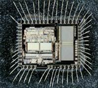
Extract ATmega64A Eeprom Code
Extract ATmega64A Eeprom Code
Most additional I/O locations are added in an Extended I/O space starting from 0x60 to 0xFF (i.e., in the ATmega103 internal RAM space). These location can be reached by using LD/LDS/LDD and ST/STS/STD instructions only when Extract ATmega64A Eeprom Code, not by using IN and OUT instructions.
The relocation of the internal RAM space may still be a problem for ATmega103 users. Also, the increased number of Interrupt Vectors might be a problem if the code uses absolute addresses. To solve these problems, an ATmega103 compatibility mode can be selected by programming the fuse M103C. In this mode, none of the functions in the Extended I/O space are in use, so the internal RAM is located as in ATmega103 mcu cracking.
Also, the extended Interrupt Vectors are removed. The ATmega64 is 100% pin compatible with ATmega103, and can replace the ATmega103 on current printed circuit boards. The application notes “Replacing ATmega103 by ATmega128” and “Migration between ATmega64 and ATmega128” describes what the user should be aware of replacing the ATmega103 by an ATmega128 or ATmega64.
By programming the M103C Fuse, the ATmega64 will be compatible with the ATmega103 regards to RAM, I/O pins and Interrupt Vectors as described above. However, some new features in ATmega64 are not available in this compatibility mode, these features are listed below.
Pin Descriptions
One USART instead of two, asynchronous mode only. Only the eight least significant bits of the Baud Rate Register is available. One 16 bits Timer/Counter with two compare registers instead of two 16 bits Timer/Counters with three compare registers. Two-wire serial interface is not supported.
Port G serves alternate functions only (not a general I/O port). Port F serves as digital input only in addition to analog input to the ADC. Boot Loader capabilities is not supported. It is not possible to adjust the frequency of the internal calibrated RC Oscillator. The External Memory Interface can not release any Address pins for general I/O, neither configure different wait states to different External Memory Address sections.
Only EXTRF and PORF exist in the MCUCSR Register. No timed sequence is required for Watchdog Timeout change. Only low-level external interrupts can be used on four of the eight External Interrupt sources. Port C is output only. USART has no FIFO buffer, so Data OverRun comes earlier. The user must have set unused I/O bits to 0 in ATmega103 programs after Read MCU.


