

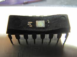
Decapsulate ATmel Chip AT89C5132 Memory Storage
2 power reduction modes are implemented in the AT89C5132: the Idle mode and the Power-down mode, These modes are detailed in the following sections which will provide better effect for decapsulate ATmel Chip AT89C5132 Memory Storage.
In addition to these power reduction modes, the clocks of the core and peripherals can be dynamically divided by 2 using the X2 mode detailed in Section “X2 Feature”.
In order to start-up (cold reset) or to restart (warm reset) properly the ATmel Chip, an high level has to be applied on the RST pin. A bad level leads to a wrong initialization of the internal registers like SFRs, Program Counter… and to unpredictable behavior of the ATmel Chip.
A proper device reset initializes the AT89C5132 and vectors the CPU to address 0000h. RST input has a pull-down resistor allowing power-on reset by simply connecting an external capacitor to VDD below figure.
Decapsulate ATmel Chip AT89C5132 Memory Storage
A warm reset can be applied either directly on the RST pin or indirectly by an internal reset source such as the watchdog timer. Resistor value and input characteristics are discussed in the Section “DC Characteristics” of the AT89C5132 datasheet.
An example of bad initialization situation may occur in an instance where the bit ENBOOT in AUXR1 register is initialized from the hardware bit BLJB upon reset. Since this bit allows mapping of the bootloader in the memory storage area, a reset failure can be critical.
If one wants the ENBOOT cleared in order to unmap the boot from the memory storage area (yet due to a bad reset) the bit ENBOOT in SFRs may be set. If the value of Program Counter is accidently in the range of the boot memory addresses then a Flash access (write or erase) may corrupt the Flash on-chip memory.
It is recommended to use an external reset circuitry featuring power supply monitoring to prevent system malfunction during periods of insufficient power supply voltage (power supply failure, power supply switched off). Idle mode is a power reduction mode that reduces the power consumption. In this mode, program execution halts if decapsulate atmel chip. Idle mode freezes the clock to the CPU at known states while the peripherals continue to be clocked (refer to Section “Oscillator”, page 12). The CPU status before entering Idle mode is preserved, i.e., the program counter and program status word register retain their data for the duration of Idle mode. The contents of the SFRs and RAM are also retained.
There are 2 ways to exit Idle mode:
Generate an enabled interrupt.
Hardware clears IDL bit in PCON register which restores the clock to the CPU.
Execution resumes with the interrupt service routine. Upon completion of the interrupt service routine, program execution resumes with the instruction immediately following the instruction that activated Idle mode.
The general-purpose flags (GF1 and GF0 in PCON register) may be used to indicate whether an interrupt occurred during normal operation or during Idle mode. When Idle mode is exited by an interrupt, the interrupt service routine may examine GF1 and GF0.
Generate a reset.
A logic high on the RST pin clears IDL bit in PCON register directly and asynchronously. This restores the clock to the CPU. Program execution momentarily resumes with the instruction immediately following the instruction that activated the Idle mode and may continue for a number of clock cycles before the internal reset algorithm takes control.