

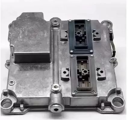
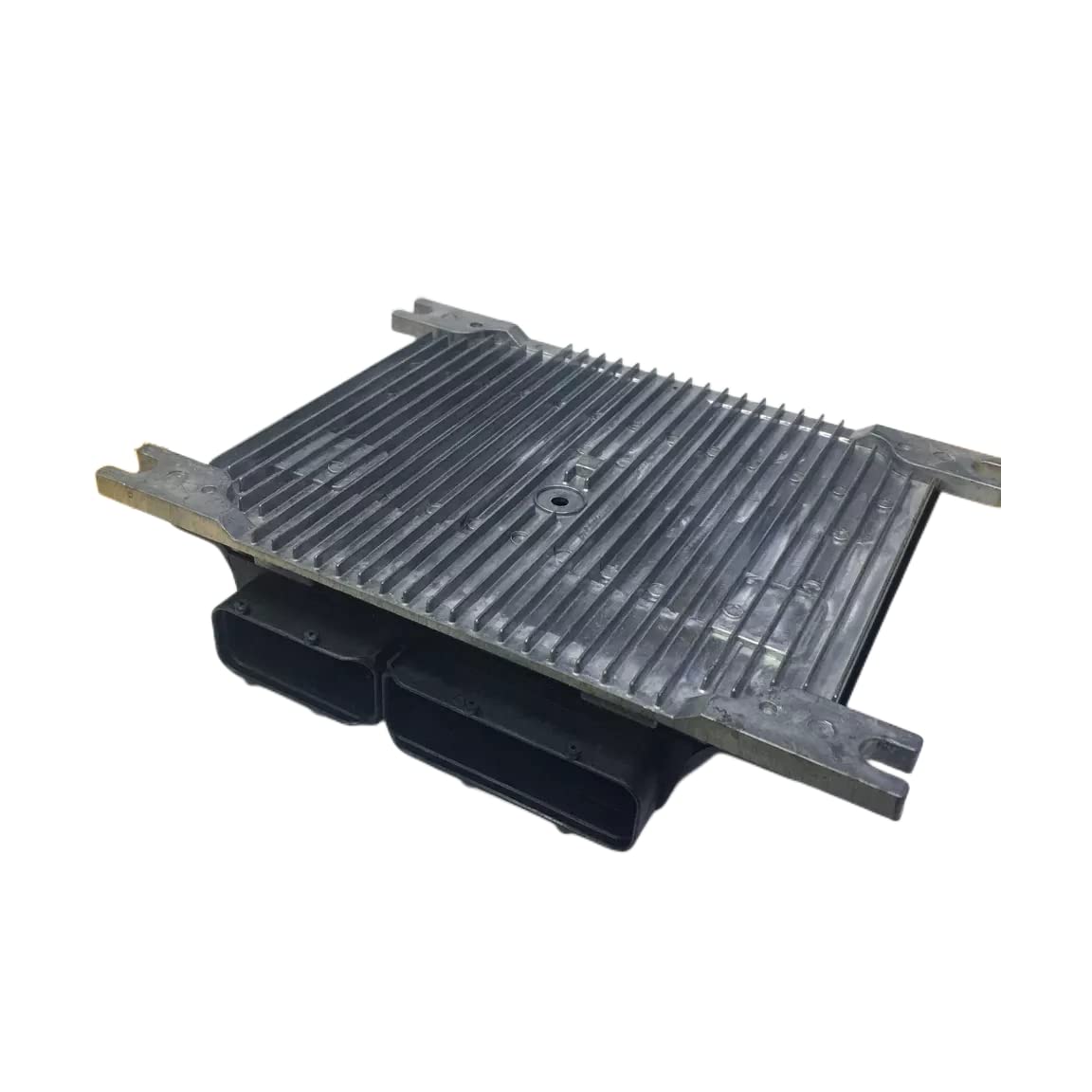
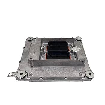
Copy Circuit Card
Copy Circuit Card is a sophisticated process widely used in the field of industrial electronics and heavy machinery repair, particularly when it comes to restoring or reproducing critical modules such as the Engine Control Unit (ECU) of an excavator. The ECU plays a vital role in monitoring and regulating engine performance — controlling parameters like fuel injection, torque output, and speed stability. When the original circuit board becomes obsolete, damaged, or unavailable from the manufacturer, the ability to recover, restore, and duplicate it through reverse engineering becomes essential for maintaining and extending the operational life of heavy-duty equipment.
The first step in the Copy Circuit Card process begins with board analysis and data recovery. Engineers inspect the original ECU card to extract information from each copper layer, using high-resolution scanning or X-ray imaging. From there, the Gerber file, schematic diagram, layout drawing, BOM list, and netlist are reconstructed to recreate an exact digital replica of the original design. This process not only preserves the connectivity between components but also ensures that all electrical characteristics—such as trace width, impedance, and grounding—are accurately reproduced.
Copy Circuit Card means the circuit card will be re-produced according to the documents extracted from physical PCB board sample which include Layout drawing, Gerber file, BOM and Schematic diagram; as one of the most important and easy to make mistake document, bill of material plays a important role for it.
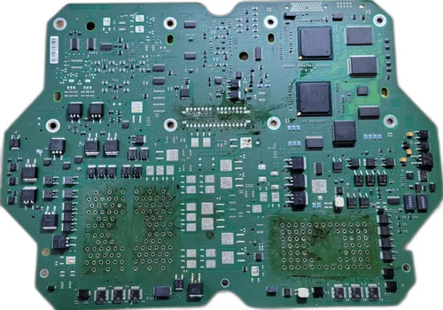
After completing the documentation phase, the bare board production begins. Using the restored Gerber files, a new printed wiring board is fabricated with the same layer structure and materials as the original ECU. It is crucial to verify alignment and hole positioning since the slightest deviation can affect connector compatibility or mounting accuracy. Following fabrication, component procurement is performed according to the BOM list, ensuring every resistor, capacitor, IC, and sensor interface matches the specified tolerance and performance grade. For automotive ECUs, components must meet industrial or automotive-grade reliability standards due to high vibration, temperature, and humidity.
Once all parts are sourced, the assembly stage begins. Components are soldered to the newly fabricated PCB using precision SMT and through-hole processes. After assembly, functional testing ensures that the recreated or refurbished ECU performs identically to the original, managing engine parameters accurately and reliably.
Translating reverse-engineered documents into real production requires careful validation. Engineers must confirm that all design files — including schematic diagrams and netlists — are error-free before mass production. Any inconsistency between the schematic and layout can result in short circuits or signal distortion. Furthermore, software or firmware compatibility should be verified, as many ECUs contain embedded control code stored in EEPROM or flash memory. Reusing or redeveloping this firmware can be one of the most challenging aspects of the Copy Circuit Card process.
Where applicable, the drawings should list the appropriate data concerning acceptance of detail parts or assemblies, as follows:
a. Dynamic tests, defining pertinent cycling, torsional deflection capabilities, and gear backlash,
b. Electrical parameters and characteristics, continuity checks, dielectric data, and durability,
c. Circuit parameters and characteristics, circuit path checks, input/output parameters, special functions, wave form analysis, and layering and bonding requirements,
d. Enclosure requirements, such as pressure and leakage allowances, (MIL-E-2036 may be used as a guide.)
e. Liquid penetrant inspections and personnel certifications, (SAE AMS2644 and NAS 410 may be used as guides.)
f. Magnetic particle inspections and personnel certifications, (ASTM E1444 and NAS 410 may be used as guides.)
g. Radiographic inspections, (SAE AMS2175, MIL-HDBK-1264, MIL-HDBK-1265, and ASTM E1742 may be used as guidance.) and
h. A review of interchangeable, moving and mating parts to ensure proper dimensions of close fitted items. ANSI B4.1 may be used as a guide.
The usage of this technique extends beyond mere duplication. It enables redevelopment, redesign, and modernization of legacy hardware, allowing older excavators and other heavy machinery to continue functioning with improved efficiency. Companies can integrate new components or redesign circuits for better thermal management or EMI resistance. However, engineers often face difficulties such as multilayer signal tracing, inaccessible buried vias, and sourcing obsolete chips.
In conclusion, Copy Circuit Card for excavator ECUs is not only a matter of cloning an existing design—it’s a meticulous engineering process involving restoration, analysis, reproduction, and quality validation. By mastering this approach, industries ensure that essential control systems remain serviceable, reliable, and ready to power the heavy machinery that keeps construction and infrastructure development moving forward.
Circuit Engineering Company Limited provide a complete PCB Reverse Engineering, PCB Clone and PCB Restoration service, Rapid Prototyping and functional test services using the latest technologies combined with traditional skills for a wide range of industries. By integrating our traditional skills with the latest technologies, we can offer clients a comprehensive portfolio of product development services all under one roof. For more details please contact our customer service team.
Tags: double side circuit card copy,flexible circuit card copy,kopiować płytki drukowanej artwork,kopiować płytki drukowanej bom,kopiować płytki drukowanej component list,kopiować płytki drukowanej diagram,kopiować płytki drukowanej gerber file,kopiować płytki drukowanej part list,kopiować płytki drukowanej schematic,multilayer circuit card copy,rigid flex circuit card copy,single side circuit card copy