Clone PCB Board Thermal Control System
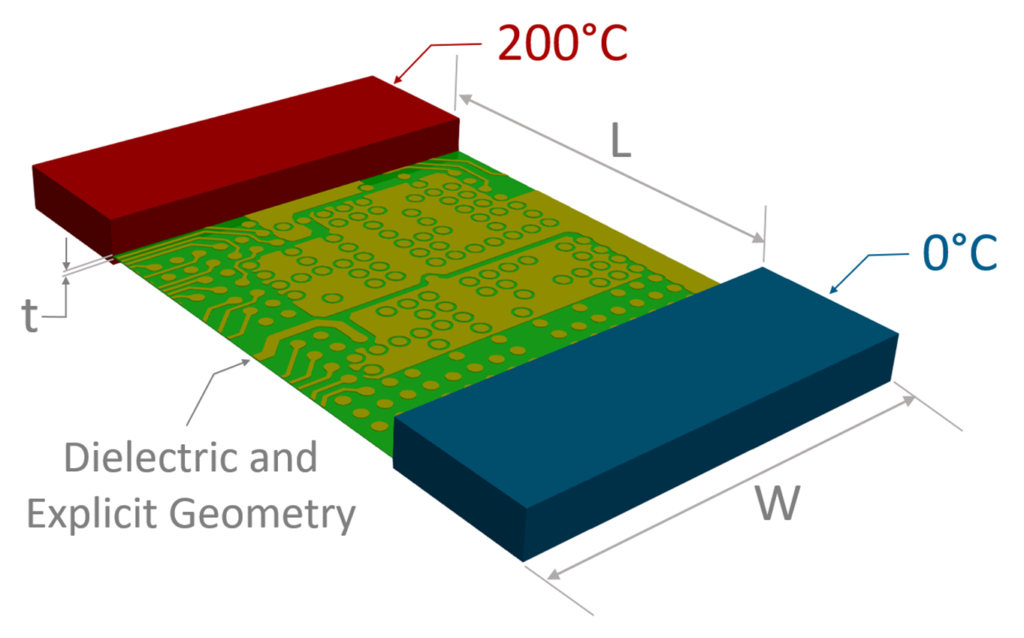
The final virtual prototyping must be performed in the expected automotive environment against single or multiple PCBs in the final product housing in order to Clone PCB Board Thermal Control System. This PCB Board Thermal Control System analysis is common in the field of mechanical design where a typical mechanical computer-aided design (MCAD) system has a complete physical definition of the product, The full definition includes enclosures, mounting methods, heat-sinks and thermal rails, and PCBs.

The PCB designer must pass the PCB board cloning design data to the mechanical designer for them to embed into the enclosure. The MCAD system needs to have complete 3D physical definition and thermal properties of components and their leads, etc., as well as all components of a complete product.
Mechanical designers then use software such as Mentor’s FloTHERM, which uses computational fluid dynamics combined with convection, radiation, and thermal conduction analysis to determine if the IC exceeds critical temperatures and may cause reliability or performance issues, and increase the heat dissipation efficiency through PCB redesign.

FloTHERM has now been extended to not only determine IC junction temperature, but also to guide designers in what may be causing problems and how to fix them. The software finds “thermal bottlenecks” to show which parts of the heat flow path are restricted. Designers can use this information to identify alternative component mounting techniques, better thermal conduction paths from the PCB to the case, etc., to alleviate bottlenecks.
Another valuable practice is to identify “thermal shortcuts,” which point to potential design options that can speed up heat dissipation. The example of Figure 2 shows the original problem of high thermal IC and the determination of shortcuts to solve the problem. Adding padding between the IC and the case in this case creates a more direct ambient heat transfer path. This simple change can reduce IC temperature by 74%.

