

Clone Multilayer Circuit Board
Clone Multilayer Circuit Board
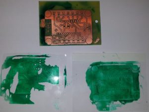
Clone Multilayer Circuit Board needs to know how many layers it has, a circuit board is built as a stack of layer pairs. Each pair starts as an insulating sheet with copper deposited on one or both sides. The copper sides of the sheet are first etched with different wiring patterns. Then the sheets are stacked into a sandwich separated by insulating material. Small holes are drilled in the the board.
Clone Multilayer Circuit Board
Finally, the holes are plated with metal, so that electrical contact is made with each layer that has copper left at hole locations. Hence, a hole can form a conductive path between two or more layers. The standard term used in PCB and chip layout for a hole is via.
Parts can be attached to boards in two ways. The classical method is to solder the pins of the components into a via pattern on the board. The other possibility is the utilization of surface mount devices, which are glued to the board. Little connection pads on the devices make contact with their counterparts on the board without penetrating it.
The first task of the physical design documents used for Clone Multilayer Circuit Board is to decide on the size of the board and on the number of layers. In practice the form factor of the board is often predetermined or at least limited by the kind of device to be built, such as a PCI slot card, for example. Hom and Granacki (1996) describe a statistics based model to estimate the number of routing layers and total wire length for a printed circuit board.