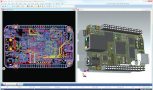
Printed Circuit Board Cloning Topology
Accompany with the accomplishment of the topology plan and critical area/high density area layout, printed circuit board cloning could probably be finished before the final topology plan. As a result of that, some of the topology routes could probably work together with the current layout. Although their priority level is still relatively low, but still need to make the electrical connection. Since a part of the plan will be generated by circling the components around it. Besides, this level of plan could probably need more details to provide other signals for necessary previlige rank.
In order to plan the databus, printed circuit board cloning designer must take some of the obstacles, design rules among each layer and other important restricted terms into account. By acquisition and understanding of these terms, they can draw the topology route accordingly.
Detail 1 has made plan for the component’s pinout definition against the top layer, and can be used to draw the component’s pinout, and connect to the topology route in detail 2. This part can be used on the printed circuit board cloning. And this part will use the un-printed area, and will only view the first layer as the circuit layer. From the perspective of printed circuit board cloning, it is quite normal to do it in this way, and the layout algorithm can use the top layer to connect to the red topology route. However, for this very special databus, some of the obstacles of automatic layout could probably provide other layer’s cloning printed circuit board option.


