

High Speed Logic in PCB Board Reverse Engineering
High Speed Logic in PCB Board Reverse Engineering
Much has been written about terminating PCB traces in their characteristic impedance, to avoid signal reflections after PCB Board Reverse Engineering. A good guideline to determine when this is necessary is as follows: Terminate the transmission line in its characteristic impedance when the one-way propagation delay of the PCB track is equal to or greater than one-half the applied signal rise/fall time (whichever edge is faster). For example, a 2 inch microstrip line over an Er = 4.0 dielectric would have a delay of ~270 ps. Using the above rule strictly, termination would be appropriate whenever the signal rise time is < ~500 ps.
A more conservative rule is to use a 2 inch (PCB track length)/nanosecond (rise/fall time) rule. If the signal trace exceeds this trace-length/speed criterion, then termination should be used. For example, PCB tracks for high speed logic with rise/fall time of 5 ns should be terminated in their characteristic impedance if the track length is equal to or greater than 10 inches (where measured length includes meanders).
As an example of what can be expected today in modern systems, below Figure shows typical rise/fall times for several logic families including the SHARC DSPs operating on +3.3V supplies. As would be expected, the rise/fall times are a function of load capacitance.
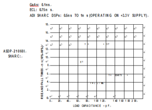
Typical DSP Output Rise Times and Fall Times
In the analog domain, it is important to note that this same 2 inch/nanosecond rule of thumb should also be used with op amps and other circuits, to determine the need for transmission line techniques which is also critical for PCB Board Reverse Engineering. For instance, if an amplifier must output a maximum frequency of fmax, then the equivalent rise time tr is related to this fmax. This limiting rise time, tr, can be calculated as:
tr = 0.35/fmax
The maximum PCB track length is then calculated by multiplying tr by 2 inch/nanosecond. For example, a maximum frequency of 100 MHz corresponds to a rise time of 3.5 ns, so a 7-inch or more track carrying this signal should be treated as a transmission line.