

Cloning PC Board Layout
The layout acquired from cloning PC Board is optimized in terms of grounding, decoupling, and signal routing and can be used as a model when laying out the ADC section of the PC board in a system. The actual evaluation board layout is usually available from the ADC manufacturer in the form of cloning pc board CAD files (Gerber files). In many cases, the layout of the various layers appears on the data sheet for the device. It should be pointed out,
though, that an evaluation board is an extremely simple system.
While some guidelines can be inferred from inspection of the cloning pc board layout, the system that you are designing is undoubtedly more complicated. Therefore, direct use of the layout may not be optimum in larger systems.
In the process of pc board cloning, Every engineer is familiar with resistors. But far too few engineers consider that all the wires and PCB traces with which their systems and circuits are assembled are also resistors (as well as inductors as well, as will be discussed later). In higher precision systems, even these trace resistances and simple wire interconnections can have degrading effects from cloning pc board. Copper is not a superconductor—and too many engineers appear to
think it is!
Below Figure illustrates a method of calculating the sheet resistance R of a copper square,
given the length Z, the width X, and the thickness Y.
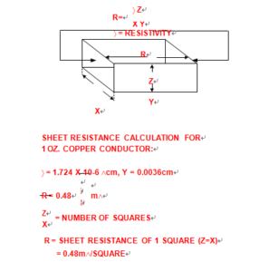
Calculation of Sheet Resistance and Linear Resistance
At 25°C the resistivity of pure copper is 1.724X10 Ω/cm. The thickness of standard.
1 ounce PCB copper foil is 0.036 mm (0.0014″). Using the relations shown, the resistance of such a standard copper element is therefore 0.48 mÙ/square. One can readily calculate the resistance of a linear trace, by effectively “stacking” a series of such squares end to end, to make up the line’s length from Printed Wiring Board Reverse Engineering. The line length is Z and the width is X, so the line resistance R is simply a product of Z/X and the resistance of a single square, as noted in the figure.