"Everything we build starts with design engineering. CECL manufactured boards for one of our products. It went perfectly – a real success.It is really an high quality service they have provided to us!"
By Nile Smith from Sinotech Inc.
“We had several very old device with obsolete boards need to be replaced –through CECL professional service.We got what we needed, and we’ve been using the results of the work without any problem till now.”
By Richard Anderson from TWP system Inc.
"Guys from CECL manufacture PCBs we use in one of our products, a clinometer and we’ve never had a problem with anything. The boards come in, they work. And, their team is very responsive."
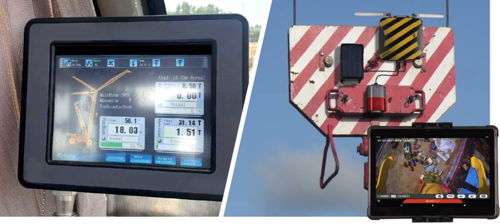
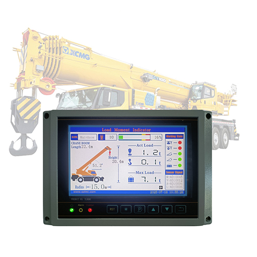
Cloning Load Moment Indicator (LMI) Controller Circuit Board is a specialized application of PCB reverse engineering focused on safety-critical electronics used in cranes and excavators. The LMI controller board plays a vital role in preventing overload, excessive reach, and tipping accidents by continuously calculating load moment based on sensor inputs. When original boards become obsolete, damaged, or unsupported by the OEM, reverse engineering provides a practical way to recover functionality and maintain equipment safety compliance.
Il processo inizia in genere con una valutazione completa di reverse engineering del PCB del controller LMI esistente. Gli ingegneri ispezionano attentamente la scheda nuda per recuperarne l’architettura elettrica, inclusi la regolazione di potenza, il condizionamento del segnale, le interfacce del microcontrollore e i circuiti di comunicazione. Attraverso un’analisi strato per strato, lo schema elettrico originale viene gradualmente ripristinato, chiarendo come i sensori di carico, gli encoder angolari e le uscite di allarme interagiscono all’interno del sistema. Una volta compresa la logica del circuito, viene ricreato il progetto fisico. Il routing delle tracce, la struttura dello stack-up e il posizionamento dei componenti vengono digitalizzati per generare un disegno di layout accurato, un file Gerber e dati di netlist convalidati. Questi documenti costituiscono la base tecnica necessaria per copiare, clonare o replicare la scheda del controller LMI con elevata fedeltà. Particolare attenzione viene prestata all’isolamento del segnale, alla strategia di messa a terra e ai percorsi di sicurezza ridondanti, poiché questi influiscono direttamente sull’affidabilità della protezione da sovraccarico. Una volta completata la documentazione, il progetto passa alla produzione della scheda nuda. Il PCB viene rifabbricato in base ai file Gerber recuperati, garantendo che la selezione dei materiali e lo spessore del rame corrispondano al progetto originale. L’approvvigionamento dei componenti segue la distinta base verificata, che specifica sensori, processori, dispositivi di memoria e componenti di protezione. Se alcune parti sono obsolete, gli ingegneri possono ricondizionare o riprogettare sezioni specifiche utilizzando alternative compatibili, preservandone al contempo il comportamento funzionale.
Cloning Electronic circuit board will refers to the mixed signals issue, especially for the current electronic consuming products, most of them have the mixed signals on the separated area after Electronic circuit board cloning and PCB designer should be aware of this point. As we all know, Electronic circuit board with mixed signal circuit which include digital circuit and analog circuit could be extremely complicate compare with other Electronic circuit board cloning. The electronic component arrangement, PCB layout as well as the power supply and grounding line treatment can directly affect the electrical performance and electro-magnetic performance after cloning Electronic circuit board. So the engineers will sufficient experience can optimize the mixed signal Electronic circuit board cloning and design features through the separation of ground and power supply circuit.
The process typically starts with a comprehensive reverse engineering assessment of the existing LMI controller PCB. Engineers carefully inspect the bare board to recover its electrical architecture, including power regulation, signal conditioning, microcontroller interfaces, and communication circuits. Through layer-by-layer analysis, the original schematic diagram is gradually restored, clarifying how load sensors, angle encoders, and alarm outputs interact within the system.
Le processus débute généralement par une analyse complète de la carte de circuit imprimé (PCB) du contrôleur LMI existant. Les ingénieurs examinent minutieusement la carte nue afin de reconstituer son architecture électrique, notamment la régulation de puissance, le conditionnement du signal, les interfaces du microcontrôleur et les circuits de communication. Par une analyse couche par couche, le schéma original est progressivement reconstitué, permettant de comprendre comment les capteurs de charge, les codeurs angulaires et les sorties d’alarme interagissent au sein du système. Une fois la logique du circuit comprise, la conception physique est recréée. Le routage des pistes, la structure d’empilage et le placement des composants sont numérisés afin de générer un schéma d’implantation précis, un fichier Gerber et une netlist validée. Ces documents constituent la base technique nécessaire pour copier, cloner ou reproduire la carte de circuit imprimé du contrôleur LMI avec une grande fidélité. Une attention particulière est portée à l’isolation des signaux, à la stratégie de mise à la terre et aux chemins de sécurité redondants, car ces éléments influent directement sur la fiabilité de la protection contre les surcharges. Une fois la documentation terminée, le projet passe à la production de la carte nue. La carte de circuit imprimé est refabriquée conformément aux fichiers Gerber récupérés, garantissant ainsi que le choix des matériaux et l’épaisseur du cuivre correspondent à la conception originale. L’approvisionnement en composants est effectué conformément à la nomenclature validée, qui répertorie les capteurs, les processeurs, les dispositifs de mémoire et les composants de protection. Si certaines pièces sont obsolètes, les ingénieurs peuvent les remettre à neuf ou les repenser en utilisant des alternatives compatibles, tout en préservant leur fonctionnalité.
Once the circuit logic is understood, the physical design is recreated. Trace routing, stack-up structure, and component placement are digitized to generate accurate layout drawing, Gerber file, and validated netlist data. These documents form the technical foundation required to copy, clone, or replicate the LMI controller circuit board with high fidelity. Particular attention is paid to signal isolation, grounding strategy, and redundant safety paths, as these directly affect overload protection reliability.
After documentation is complete, the project moves into bare board production. The PCB is remanufactured according to the recovered Gerber files, ensuring that material selection and copper thickness match the original design. Component procurement follows the verified BOM list, which specifies sensors, processors, memory devices, and protection components. If certain parts are obsolete, engineers may refurbish or redesign specific sections using compatible alternatives while preserving functional behavior.
Assembly and testing are critical stages before deployment. Newly assembled boards are electrically tested and functionally validated under simulated load conditions to ensure accurate moment calculation and alarm triggering. Only after passing these checks can the reverse-engineered design be safely reproduced or duplicated for field use.
Der Prozess beginnt typischerweise mit einer umfassenden Reverse-Engineering-Analyse der vorhandenen LMI-Controller-Leiterplatte. Ingenieure untersuchen die Leiterplatte sorgfältig, um ihre elektrische Architektur zu rekonstruieren, einschließlich Spannungsregelung, Signalaufbereitung, Mikrocontroller-Schnittstellen und Kommunikationsschaltungen. Durch eine schichtweise Analyse wird das ursprüngliche Schaltbild schrittweise wiederhergestellt und die Interaktion von Lastsensoren, Winkelgebern und Alarmausgängen im System verdeutlicht. Sobald die Schaltungslogik verstanden ist, wird das physische Design nachgebildet. Leiterbahnführung, Lagenaufbau und Bauteilplatzierung werden digitalisiert, um präzise Layoutzeichnungen, Gerber-Dateien und validierte Netzlisten zu generieren. Diese Dokumente bilden die technische Grundlage für die hochpräzise Kopie, das Klonen oder die Replikation der LMI-Controller-Leiterplatte. Besonderes Augenmerk liegt auf der Signalisolierung, der Erdungsstrategie und redundanten Sicherheitspfaden, da diese die Zuverlässigkeit des Überlastschutzes direkt beeinflussen. Nach Abschluss der Dokumentation beginnt die Leiterplattenfertigung. Die Leiterplatte wird anhand der rekonstruierten Gerber-Dateien neu gefertigt, wobei sichergestellt wird, dass die Materialauswahl und die Kupferdicke dem Originaldesign entsprechen. Die Komponentenbeschaffung erfolgt anhand der verifizierten Stückliste, die Sensoren, Prozessoren, Speicherbausteine und Schutzkomponenten spezifiziert. Sollten bestimmte Teile veraltet sein, können Ingenieure einzelne Abschnitte mit kompatiblen Alternativen überholen oder neu konstruieren und dabei die Funktionalität erhalten.
If engineers have suspect on the design unique grounding for Electronic circuit board with mixed signals, the way to cut off the grounding layer to adjust the Electronic circuit board layout before Cloning Electronic circuit board, but in the process of Cloning Electronic circuit board, engineer should pay sufficient attention on layout of Electronic circuit board to ensure the board can be connected by a jump with less than 0.5 inch length or 0 OHM resistor. And make sure the engineer can tell the separated areas and layout, to ensure no digital signal line above the analog part or any analog signal line above any digital part. However, any one of signal lines can’t cross the space among grounding or cut off the space between power supply grounds when Cloning Electronic circuit board. If it is necessary to test the Electronic circuit board functionality and Electronic Magnetic Cross features, and connect two grounds through 0 OHM resistor or jump together after printed circuit board clone, recheck the Electronic circuit board functionality and Electronic Magnetic Cross features. Compare the test result, it will come out that almost in all of the situations, united grounds solution could be more advanced than separated grounds in the aspect of Electronic Magnetic Cross features.
Converting restored documents into real production requires disciplined quality control. Manufacturing tolerances, calibration procedures, and regulatory considerations must be addressed during redevelopment. The primary usage of this technique is lifecycle extension of heavy machinery, cost reduction, and rapid spare-part availability. However, challenges such as multilayer complexity, proprietary firmware interfaces, and stringent safety requirements can arise.
El proceso suele comenzar con una evaluación exhaustiva de ingeniería inversa de la placa de circuito impreso (PCB) del controlador LMI existente. Los ingenieros inspeccionan cuidadosamente la placa base para recuperar su arquitectura eléctrica, incluyendo la regulación de potencia, el acondicionamiento de señales, las interfaces del microcontrolador y los circuitos de comunicación. Mediante un análisis capa por capa, se restaura gradualmente el diagrama esquemático original, lo que aclara cómo interactúan los sensores de carga, los codificadores de ángulo y las salidas de alarma dentro del sistema. Una vez comprendida la lógica del circuito, se recrea el diseño físico. El enrutamiento de las trazas, la estructura de apilado y la ubicación de los componentes se digitalizan para generar un plano de diseño preciso, un archivo Gerber y datos de lista de conexiones validados. Estos documentos constituyen la base técnica necesaria para copiar, clonar o replicar la placa de circuito impreso del controlador LMI con alta fidelidad. Se presta especial atención al aislamiento de la señal, la estrategia de conexión a tierra y las rutas de seguridad redundantes, ya que afectan directamente la fiabilidad de la protección contra sobrecargas. Una vez completada la documentación, el proyecto pasa a la producción de la placa base. La PCB se remanufactura según los archivos Gerber recuperados, garantizando que la selección de materiales y el espesor del cobre coincidan con el diseño original. La adquisición de componentes se realiza según la lista de materiales verificada, que especifica sensores, procesadores, dispositivos de memoria y componentes de protección. Si ciertas piezas están obsoletas, los ingenieros pueden reacondicionar o rediseñar secciones específicas utilizando alternativas compatibles, preservando su funcionalidad.
When executed correctly, cloning an LMI controller circuit board delivers a reliable, compliant solution that supports operational safety while maximizing the value of existing crane and excavator assets.