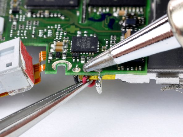
Reverse Engineering Printed Circuit Board Decoupling
Reverse Engineering printed circuit board decoupling is a process to improve the PCB board performance through schematic diagram modification.

So there will be a topic about electronic decoupling installation on the printed circuit board, in the direct current power supply revert route, overload alteration will cause power supply noise in the process of PCB card reverse engineering.
Such as in the process of reverse engineering high speed circuit board, when the status of a circuit switch to another one, it will cause a great peak current on the power line, and give rise to the transient noise voltage. Install the decoupling capacitor on the electronic pc board can help to depress the noise generated from overload, and it is also one of the most reliable way according to below principle:
Power supply input terminal can connect to a 10 to 100UF electro, if the location of electronic board is allowable, engineer can apply over 100UF or above electro which will have a better performance on anti-interference; equip each integrated circuit chip with a 0.01UF ceramic capacitor, if the PCB board has too few space to install them, can install the tantulum electro each 4 to 10 piece of chips, and these chips all have low resistance value for high frequency, within the scope of 500KHZ to 20MHZ, its impedance should be lower than 1 ohm, and with small leak current.
Tags: reverse engineering circuit board,reverse engineering circuit card,reverse engineering pcb,reverse engineering pcb assemble,reverse engineering pcb board,reverse engineering pcb card,reverse engineering pcba,reverse engineering printed circuit board,reverse engineering printed wiring board,reverse engineering pwb,reverse engineering pwba

