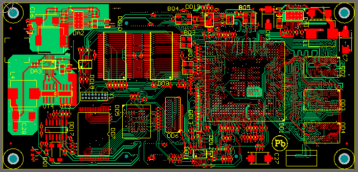
Reverse Engineering PCB For its Layout Drawing
Now Place a CON3 in the upper left corner (mirror it as well). Connect Wire Segments to Pins 1 and 2. Engineer will use this as a power connector for Reverse Engineering PCB. Select Place/Power Port, and go to properties. Select a Net of VCC, and use the Bar Style.

Connect it to Pin 1. Place another Power Port – use a Power Ground Style, and call it GND. Connect it to pin 2.
Power Ports are essentially Net Names with special symbols – they also will connect separate nodes on the page. Use Place/Place Directive/No ERC on pin 3 – this tells Protel nothing should be connected to that pin.
We use a 3 Pin Connector for power even though there are only two connections. This will ensure that even if we accidentally plug in the connector backwards, that we will not destroy the PCB board in the process of Reverse Engineering PCB. Keeping in mind that your creating a physical PCB board and thinking ahead on how it will actually be used will save a lot of time when actually working with the PCB layout drawing.
Also place a CON1 – connect a wire and net name to it called ENABLE. We will now place AND Gates in the design. To do this we need to use another library. Click Add/Remove under the Library Window. The Protel Schematic Libraries are in C:\Program Files\Design Explorer 99SE\Library\Sch. Double-Click on NSC Databooks.DDB and then click OK. Several more Libraries are now available. Select CMOS Logic Databook 1988, and then double click MM74HC08 – an AND Gate.
Using the filter will allow you to find it quicker – enter in the Filter Window *08*. Place one of the devices into the design from Reverse Engineering PCB, and extend wire segments from the nodes. Then click and drag until the gate and wires are surrounded by the outlined box, and let go. The symbols will be selected and therefore be outlined in yellow, and can be copied. You can select a single component by holding shift and then clicking it. Merely clicking a symbol and having a dashed outline will let you delete it, but not let you copy it to the clipboard. Press CTRL-C to copy and click the mouse on the start of one of the wire segments – when you paste the symbols, they will be oriented from this location. The symbols can be deselected by holding X and then pressing A.

