

Printed Wiring Board Cloning
Printed Wiring Board Cloning can help designer to extract the schematic diagram out from the physical Printed wiring board through its layout, so it is necessary to know the basic opetional techniques of how to operate the Protel Software, below we would like to introduce some methods:
New lines can be restricted to 45 degree angles if desired. You can toggle this restriction on and off while creating lines by pressing the period key. If the 45 degree restriction is turned on, then the / (forward slash) key can be used to cycle through three different modes of 45 degree line creation. One mode just creates a single line forced to the nearest 45 degree vector. The next mode creates two lines from the start to end points such that the first line leaves the start point at a 90 degree vector, and the second line enters the end point on a 45 degree vector. The last mode creates two lines such that the first line leaves the start point on a 45 degree vector and arrives at the end point on a 90 degree vector.
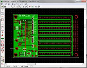
design software which can help for Printed Wiring Board Cloning
You can temporarily swap between the last two modes by holding the Shift key down. It is simple to edit a line object by breaking it into pieces (insert point mode), moving an end point or the whole line (Arrow tool ), or changing the layer it resides on (M key moves the line under the pointer to the active layer). In the case when two line segments meet at exactly the same point you can delete the intermediate point, otherwise the delete tool removes an entire line. Feel free to experiment will allow you to undo and redo anything that materially affects your work. If you switch active layers in the midst of placing lines a via will automatically be placed, when necessary, in order to continue the connection.
If you draw a line inside a polygon, it will either plow through the polygon creating a clearance, or touch the polygon. This behavior is selectable in the Settings menu for new lines. To change the behavior of an existing line, hit the J key with the cross hair over the line. You can increase the size of the clearance by 2 mils on each edge with the with the K key. Shift-K will decrease the clearance by 2 mils. The increment may be changed from 2 mils through the application resource file. The clearance can be also increased, decreased and set by the Change ClearSize action.
Lines do not need to intersect the center of a pin, pad, via, or other line for Printed wiring board Cloning to understand that they make electrical connection. If the connection is too tenuous, running the design rule checker will report that the connection may break if the line width shrinks slightly.
Tags: cloning printed wiring board artwork,cloning printed wiring board bom,cloning printed wiring board component list,cloning printed wiring board design,cloning printed wiring board diagram,cloning printed wiring board drawing,cloning printed wiring board gerber file,cloning printed wiring board layout,cloning printed wiring board part list,cloning printed wiring board schematic