

PCB Circuit Card Copying
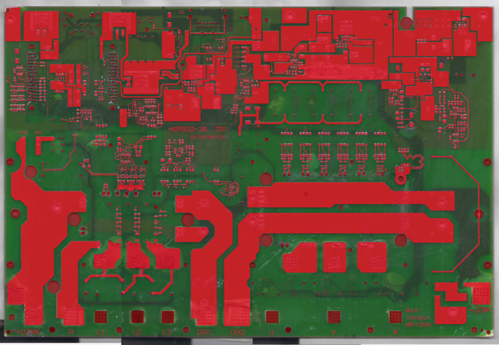
PCB Circuit Card Copying is a process to extract PCB board layout design, gerber file, and schematic diagram out from physical printed circuit board sample, and reverse engineering the electronic circuit board through these documents;
An Arc from printed circuit board copying is drawn with the arc-tool. Get there either by selecting it from the Tool palette or by pressing <Key>F8. Press Btn1 to define the starting point for the arc. Drag the mouse towards the desired end point along the path you want the arc to follow.
The outline of the arc that will be created is shown on the screen as you move the mouse. Arcs are always forced to be 90 degrees and have symmetrical length and width ( i.e. they are a quarter circle). The next Btn1 click creates the arc. It will have the same width as new lines (displayed in the status line) and appear on the active layer.
The arc leaves the starting point towards the cross hair along the axis whose distance from the cross hair is largest. Normally this means that if you drag along the path you want the arc to follow, you’ll get what you want. If the grid is set to the arc radius after Pcb circuit card reverse engineering, then the two distances will be equal and you won’t be able to get all of the possible directions.
If this is thwarting your desires, reduce the grid spacing (!Shift<Key>G ) and try again for the next task. A polygon is drawn by defining all of its segments as a series of consecutive line segments. If the first point matches a new one and if the number of points is greater than two, then the polygon is closed. Since matching up with the first point may be difficult, you may use Shift<Key>p to close the polygon. The Shift<Key>p won’t work if clipping to 45 degree lines is selected and the final segment cannot match this condition.
I suggest you create simple convex polygons in order to avoid a strong negative impact on the performance of the connection scanning routines. The rectangle-mode is just an easy way to generate rectangular polygons. Polygon-mode also is selected by <Key>F6 whereas rectangle-mode uses <Key>F4.
Pressing a <Btn1> at two locations creates a rectangle by defining two of its corners. <Key>Insert brings you to insert-point-mode which lets you add additional points to an already existing polygon. Single points may be removed by moving the cross hair to them and selecting one of the delete actions (remove-mode, BackSpace, or Delete. This only works if the remaining polygon will still have three or more corners.
Tags: copying pcb circuit card artwork,copying pcb circuit card bom,copying pcb circuit card component list,copying pcb circuit card design,copying pcb circuit card diagram,copying pcb circuit card gerber file,copying pcb circuit card layout,copying pcb circuit card part list,copying pcb circuit card schematic